Continue to Site

Eng-Tips is the largest engineering community on the Internet

Intelligent Work Forums for Engineering Professionals

  • Congratulations waross on being selected by the Eng-Tips community for having the most helpful posts in the forums last week. Way to Go!

Fdtn Overturning Calcs-How to treat an uplift load mathematically.

Status
Not open for further replies.

Ron247

Structural
Jan 18, 2019
1,182
My main question has to do with how you mathematically treat an uplift load when doing overturning calcs. I have seen 2 different ways but they do not yield the same answer. Currently I am reviewing an older structure for new loads but the old design did not calc them the same as I do. Just thought I would see how the Eng-Tips world does it. I have always used all stabilizing forces divided by all destabilizing forces as the formula for FOS. This is definitely the conservative method. I have seen many times where they are treated as net forces and then the FOS is calculated.

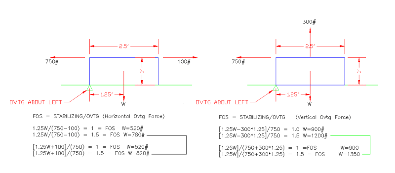
The attached drawing shows a fdtn with a horizontal and vertical applied forces. The upper set of calcs is net forces while the lower set is (all stabilizing/all destabilizing). The 2 methods do not matter if the FOS is 1. It only matters when the FOS is not 1.

Just curious how this is treated by others. The more loads and the higher the FOS is, the more the footing weight amount differs.

Also would like a good layman's explanation of how the 300# vertical load can cause overturning about the left and right sides simultaneously. Other than statics says it will. It seems that if the fdnt is not truly attached to the ground on one of the sides, it would only create uplift but not overturning. In that situation, the net force method seems appropriate to some degree.

CAD_Dwg_fhgazw.png
 
Replies continue below

Recommended for you

1.
Mstab = 1.25W +100​
Mot = 750​
FOS = Mstab/Mot = (1.25W + 100)/750​
Alternatively, W = (750*FOS -100)/1.25​
if FOS = 1, W = (750-100)/1.25 = 520​
if FOS = 1.5, W = (1.5*750 - 100)/1.25 = 820​

2.
Mstab = 1.25W​
Mot = 300*1.25 +750​
FOS = Mstab/Mot = 1.25W/(300*1.25 + 750)​
Or W = FOS(300*1.25 + 750)/1.25​
if FOS = 1, W = 900​
if FOS = 1.5, W = 1350​


BA
 
Ron247 said:
Also would like a good layman's explanation of how the 300# vertical load can cause overturning about the left and right sides simultaneously. Other than statics says it will. It seems that if the fdnt is not truly attached to the ground on one of the sides, it would only create uplift but not overturning. In that situation, the net force method seems appropriate to some degree.

If the 750# horizontal force is removed, then Mstab = 1.25W and Mot = 1.25*300
FOS = 1.25W/1.25*300 or W/300, hence W = 300*FOS
if FOS = 1.0, W = 300, and the footing is just balanced. There is no net uplift and zero pressure along the bottom of footing. The footing is just floating in space.
if FOS = 1.5, W = 450#, so the 300# uplift created pure uplift and no overturning, but the factor of safety is against liftoff rather than overturning.

BA
 
Ron247:
Every time we start adding load factors (various adjustment factors, and sometimes of different values to boot) to some loads, but not to all loads; all logic, common sense and simple math start to go out the window. You just use the code methods, formulas, etc., and follow the cookbook. You don’t have to know what you are cooking, or how much a pinch of salt is, just follow the damn cookbook formula/recipe, and quit all that thinkin and logic crap. You don’t have to know how things work or go together any more, the codes are set up so anyone who can read them, and perfectly interpret their ever increasing complexity, can pretend to be an engineer. God help us. Just read 50% of the questions here on E-Tips, they are getting dumber and dumber by the week. Where is the code formula or section to do this or that, and of course, ‘this’ isn’t described in anything approaching engineering speak.
 
The main way that I look at this is to look at the load source and group that together. If WL has a shear, axial force and moment, then I take the combined action of those three as the de-stabilizing effect. Then the combined effect of gravity load as the stabilizing effect.

That way, the safety factor is exactly that. A factor of safety. If I have a factor of safety of 2.0, then I should be able to multiple the destabilizing load by 2.0 and get a foundation that is just barely unstable.

We had a thread some years ago that was pretty similar. I give an example in that one related to an uplift case and why I think this method (which I have called the "true safety factor" method) is better. I'll let you read that thread and come to your own conclusions.

 
BA: It looks like your calcs indicate all stabilize/all destabilize rather than net force.

Josh: I am not sure what you are stating. I assume by gravity loads you mean all gravity loads, not the footing weight. There are instances where the gravity loads destabilize the same as wind load. One example is a lumber shed that has a fixed base column and a rafter as depicted below. In that example, I cannot separate the forces (Fy,Fx, Mz) by load case because Mz could be the same sign for DL+WL if I make the shed tall with a short rafter as compared to short with a long rafter. I tend to draw all loads regardless of load case source and then choose the stabilizing and destabilizing.

Lumber_shed_kyithq.png
 
I get the feeling JoshPlum was involved in the RISAFDN overturning and stability calculations strategy.

ETA Link.

RISA Link
 
Azcats -
Yes, I was the one who developed the RISAFdn overturning strategy. Though I did not come up with the method. It was developed over years of feedback from users of RISAFoot. Some pointing out how the original method / traditional method was incorrect for cases where uplift occurs.

Ron -
Two cases for your example:
1) If you're looking at your WL + DL case, then the true safety factor method will still be correct. Either for a wind uplift or a wind downward load.... with the idea being the safety factor should represent the multiplier on the destabilizing load (WL) that would cause instability.

2) For a dead load only case, proper way to do this would be to separate this load into two parts... The stabilizing part and the overturning part. The most common case that I saw (when working on petrochem projects) was a vertical vessel with a re-boiler that hung off of one side. In that case, the weight of the main vessel would all be considered stabilizing, but the weight (and resulting moment) of the re-boiler would both be considered de-stabilizing. That way, the Safety Factor would be how much you could multiple the Re-Boiler by before the footing becomes unstable. It wouldn't work out that way if you considered the weight of the re-boiler to be a stabilizing effect.

The case you show, where the ONLY dead load has a de-stabilizing effect is the one case where the true safety factor method breaks down. In that case, it makes sense to revert to the traditional method (combine all axial forces together to come up with a stabilizing effect and combine all the moment together to come up with a de-stabilizing effect).

 
From reading the RISA link description, it sounds like True FOS is the same of similar to the 2nd way I show the calcs. I use the 2nd method I show. I am trying to find out if that is the consensus method. I have never made any assumptions about what would stabilize or destabilize based on whether the load is gravity versus wind nor have I chose them based on whether they are vertical or not. I just show the all the loads on the footing and decide if they stabilize or destabilize based on what movement I am checking. I do not use net forces where I add all horizontals or add all verticals and then do my FOS.
 
I typically just break it up using a constant sign convention.

So for your example of sum of moments about the left bottom corner I would say positive moments are clockwise and anything that creates a negative moment gets lumped into the de-stabilizing bin and anything that creates a positive moment dumps into the stabilizing bin.

If your applying the applicable load combinations from IBC checking for a FOS isn't really a thing anymore because it is baked into the load factors, although I'm pretty sure a vast majority are still doing it and taught checking with a factor of safety.

Open Source Structural Applications:
 
I don't know that there is any "consensus method". But, if there is, then it's closer to the "traditional method" which is to take all the vertical loads together (as a stabilizing load) and all the lateral forces and moments together (as the destabilizing load). But, others may define the traditional method differently.

The "True Safety Factor Method" was developed specifically to address some concern some users had over the more widely used method. For the majority of the cases the methods should be pretty close. It's usually for uplift cases where the two methods start to diverge.... And, that's where I think the True Safety Factor method gives better results.
 
Mathematically the net force method is incorrect.

For your case II, taking the lateral force out, with coincident but opposite forces as shown, Uplift = 300, for SOS = 1, we know W = 300 by inspection. FNET = 300 - 300 = 0, MR = 1.25 * 0 = 0, MOT = 0, SOS = 0/0 = ∞, safety factor is undefined. This holding true for all cases with weight greater than the lift force.

For weight less than the uplift force, FR = 0, SOS = 1.25*0/(1.25*FNET) = 0

I may have misunderstood the "net lift method". Please advise.
 
Status
Not open for further replies.

Part and Inventory Search

Sponsor