Mahmoud Elgharib
Student
Hello all,
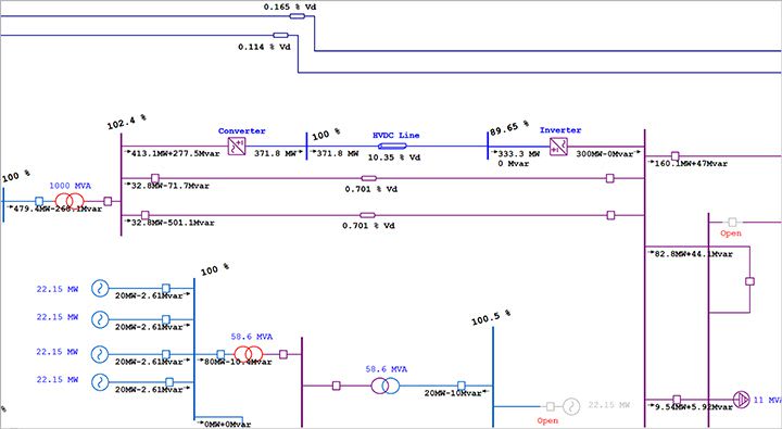
I've been assigned to perform a simulation on ETAP comparing a normal transmission's lines power capability to that of a HVDC. After filling in all the data required and performing a load flow. The first scenario where the AC line is connected is successfully done whereas the one with the HVDC doesn't display any power flow at all from the point of connection of the HVDC link towards the end of the network. It's as if nothing is connected at all from the point of the HVDC link.
Does anyone have any experience using the software who could maybe let me know what is happening here?
(For those who are not familiar with the software, all values for the rectifiers and the inverters are included inside the model block aswell.)
Thank you.