On stand alone standby generator, the governor controls the speed between 100% of rated speed at full load to 103% of rated speed at no load.
There are exceptions, but those settings have worked well for years.
Grid tied generator governors control between 100% at no load and 105% at full load, but they don't.
That is The governor is configured to control between 100% and 105% (5% droop), but the grid locks the speed at 100% plus or minus small variations.
So how do you control the load? With the governor set at 100%, the generator idles on-line but doesn't contribute any energy.
As the governor setting is increased, the generator picks up load until at a governor setting of 105% the set is developing rated output.
When many generators are connected in a grid, one generator, called the swing set, responds to load changes on the grid.
All of the other generators run at fixed output.
If the load on the swing set is dropping too far, or rising too far, load dispatch will cause one or more of the base load sets to reduce their output or to drop off line.
A long time ago, I was visiting a very old hydro plant. The generators were running at about 10% output.
Running at low output is better than shutting down completely. It keeps the alternators warm and dry.
One operator was on duty.
The phone rang.
It was the load dispatch center.
"Please take your sets up to 80% load."
The plant was so old that everything was manual. There was not even an Automatic Voltage Regulator.
The operator turned a switch on the control board.
WE could see on the machine room floor, a very large hydraulic cylinder start to extend and push on a very large bell crank.
That opened the gate and allowed more water to flow through the turbine.
As the output increased without a corresponding increase in excitation, the power factor dropped. (On a stand alone set, the voltage would drop, but when connected to the grid, one set has little control over grid voltage and the PF drops instead.
The operator left the switch controlling the hydraulic solenoid and moved to a rheostat.
He manually increased the excitation until the PF was satisfactory.
Back to the hydraulic control and pick up more load.
Over to the rheostat and increase the excitation.
Rinse and repeat.
It was a unique experience to see operations that are normally done automatically done completely manually.
A few years later the plant was completely automated and there was no longer a local operator. Everything was done remotely by the load dispatch center.
The plant was eventually taken out of operation and became a visitors center.
[URL unfurl="true" said:
https://dbpedia.org/page/Stave_Falls_Dam_and_Powerhouse[/URL]]Stave Falls Dam is a dual-dam power complex on the Stave River in Stave Falls, British Columbia, Canada. The dam was completed in 1912 for the primary purpose of hydroelectric power production. To increase the capacity of Stave Lake, the dam was raised in 1925 and the Blind Slough Dam constructed in an adjacent watercourse 500 m (1,600 ft) to the north, which was the site of the eponymous Stave Falls. In 2000, the dam's powerhouse was replaced after a four-year upgrade. The original Stave Falls powerhouse was once British Columbia's largest hydroelectric power source, and is a National Historic Site of Canada. (en)
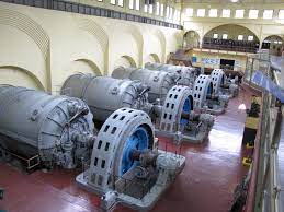
HERE IS THE ORIGINAL TURBINE HALL
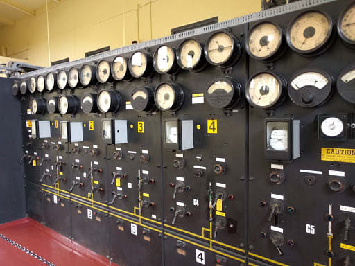
THE ORIGINAL MANUAL CONTROL BOARD
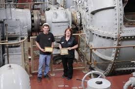
RELATIVE SIZE
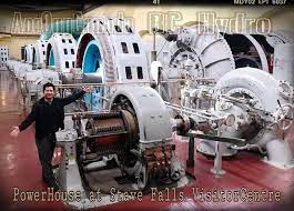
EXCITER GENERATOR AND WATER WHEEL DRIVING IT
--------------------
Ohm's law
Not just a good idea;
It's the LAW!