itsmoked said:
I'm very sensitive to water/electricity issues. I've done calls on boats that had problems. In one case a death from someone diving into the water next to a 'bad boat'. In another case someone was paralyzed but their inertia carried them out of the potential gradient, essentially back to life. So when someone talks about problems with electrical equipment associated with water works I get concerned. The very first thing done is to make absolutely sure there's no mains voltage during any part of the process modes in the solution (pump(s) on/off). Brine might as well be liquid metal as far as mains currents are concerned.
I can't argue with huge respect for electrical safety. In my mind if we have this concern then the motor frame and pump casing should be viewed with the same level of concern as the water since the only possible path for line voltage in the water is from stator winding to stator frame to pump casing (line voltage can't get on the rotor)
Maybe some voltage measurements help along the way for checking both for safety and for understanding the problem.
Voltage measurements should have one lead of the meter connected to ground (not any circuit common). itsmoked gave a procedure including using the ground socket on a 3-prong extension cord plugged into a 3 wire outlet (his initial check validates you have a ground connection by checking for 120 volt).
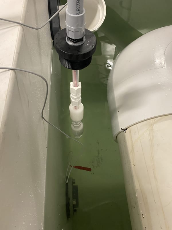
You could check the water to ground as suggested. It would also be interesting to check the motor frame to ground and pump frame to ground and that metal flange a few feet from the pump to ground.
I know it seems like motor casing should be 0 voltage to ground but if the grounding is not effective as Keith mentioned you might still see a voltage from high frequency there.
Data is always good. But of course there is always a caveat. There is always the possibility to see a voltage due to the large loop area involving the test leads and the things they’re connected to and any path that in turn connects those two things.
RedSnake said:
It would be a easy test putting the probe in a glass bottle with freshwater just holding it in the tank to see if it makes any difference.
I see now that test would separate the effects of resistive conducted current (cannot flow through glass) from capacitive current (can flow through the glass). I did a calc (attached) based on the end-to-end resistance and capacitance in a pipe (assuming seawater conductivity 6 mho/m) and I now think the resistive conduction is far more important than the capacitive conduction in the water (by the way the selection of pipe length and diameter and number of pipes are all irrelevant to this particular conclusion since they cancel out in product R*C, but it was still interesting for me to put them in to see the individual R and C values in order to estimate what current might flow). So I suspect your test would cause the indication problem to go away. If the delay associated with temperature measurement in that configuration is considered acceptable (I don’t know, it might not be) it might possibly end up considered a permanent solution to the level indication problem. Would be better than a grounded can with holes.
(EDIT I rechecked my conductivity calc, and it was correct, but the comment "ohm/m" should have been mho/m... if you want to play with that file yourself it is available on smath cloud
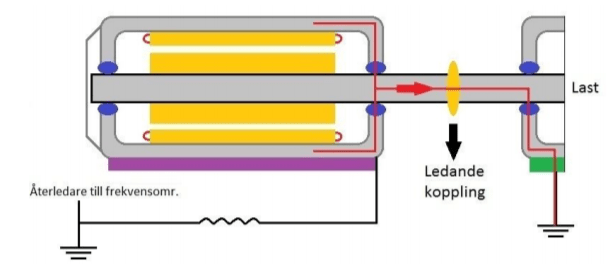
To summarize the two potential paths for current to flow:
1 - stator winding capacitively coupled to rotor then conducted through coupling to pump impeller. This path could be solved by shaft grounding (which also improves bearing life) or by insulated coupling.
2 - stator winding capacitively coupled to stator frame then conducted to pump casing. this path might be solved by improving ground connections at the motor.
If we're looking for other quick-check solution I would try grounding that flange a few feet away from the pump, I don't see any harm in that myself.
=====================================
(2B)+(2B)' ?
![[lol]](/data/assets/smilies/lol.gif "[lol] [lol]")

![[bigsmile]](/data/assets/smilies/bigsmile.gif "[bigsmile] [bigsmile]")
![[ponder]](/data/assets/smilies/ponder.gif "[ponder] [ponder]")
![[dazed]](/data/assets/smilies/dazed.gif "[dazed] [dazed]")