pylfrm,
The secondary datum feature B is referenced with the implied RMB condition in these examples, and we are told that the simulator progresses from the LMB to the MMB to make maximum contact. I take it that this is what you're referring to.
It is true that the tolerance on the datum feature affects where the simulator starts and stops. The larger the profile tolerance on the datum feature, the larger the range that the simulator progresses through.
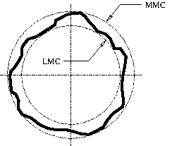
Actually, I don't really like this either. The underlying assumption that Y14.5 uses is that datum feature simulators conform to their tolerances. The simulator behavior is defined only in the range of conformance of the datum feature. What happens if we get a part whose secondary datum feature B doesn't conform to its profile tolerance? Or whose primary datum feature A doesn't conform to its size tolerance?
This issue is even more significant for MMB (and LMB) references. The simulator is defined as fixed at the MMB condition of the datum feature. What happens if the datum feature is nonconforming, and violates the MMB condition? Do we just stop, and say that the tolerance is nonconforming because the datum feature is nonconforming? If so, this is extremely limiting.
I believe that this assumption came from the context of hard gages. If the datum feature goes past its MMB, the part won't fit on the gage and so the part fails. If the datum feature goes past its LMB, it's too loose and so the part should fail. But I would say that Y14.5 needs to update this, and allow the scenario of a datum feature being nonconforming.
Evan Janeshewski
Axymetrix Quality Engineering Inc.

