Continue to Site

Eng-Tips is the largest engineering community on the Internet

Intelligent Work Forums for Engineering Professionals

  • Congratulations IRstuff on being selected by the Eng-Tips community for having the most helpful posts in the forums last week. Way to Go!

Edge cover to vertical hook in slab top bar 1

Status
Not open for further replies.

ajk1

Structural
Apr 22, 2011
1,791

The following is asked with respect to our ongoing review of all of our standard typical details, and not with respect to any particular project.

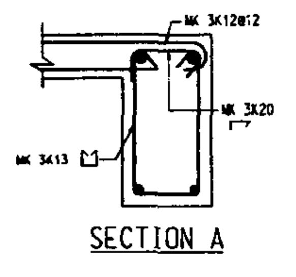
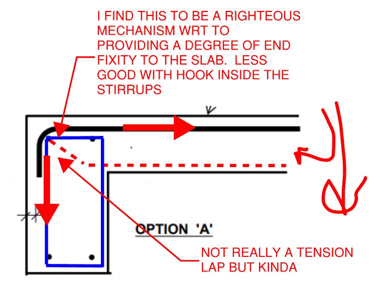
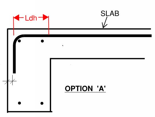
1. What is the standard cover that would be specified to the vertical downward hook of top bars in one-way slab at the floor edge supporting spandrel beam?
In other words, should the slab vertical hook be placed to the outside of the supporting beam top bars (which may in some cases require moving the beam top bars more away from the exterior face of the beam (depending on the slab bar diameter), or inside of those bars?


Would that be shown in the ACI Detailing Manual (a copy of which I can't find at the moment locate).


3. If the slab bottom bars were extended to the exterior face of the supporting spandrel beam and hooked up vertically with a standard hook, would it be appropriate to specify the same cover as the top bars?
 
Replies continue below

Recommended for you

Uh oh... did we leave you for dead on the field of Eng-Battle? That will never do.

1) I believe that the hook cover is technically the same as the bar cover to the top of the slab. So 3/4" or 1", not 1-1/2".

2) I detail my slab hooks to land outside the beam longitudinal bars, either in the plane of the stirrups or a little out side of that based on #1.

3) The sad, grainy detail below is from the ACI detailing manual. That said, it's not exactly conclusive and I doubt many people are running 180's on the slab bars.

4) In the absence of some compelling reason to do otherwise, I keep my slab-edge top bars to #5/15M max. Pretty tight radius bend on those.

5) I expect my beam longitudinal bars to be placed at the top of the stirrup cage which, as a result of the stirrup bends, puts them inboard a bit to begin with.

6) #1 + #3 + #5 = I don't seem many occasions where the beam flexural bars need to be pushed in. And I leave plenty of space for them either way.

7) Mechanically, I have a slight preference for taking the hooks to the outside of the cage per the sketch below. Of course, I tend to have something to say about every damn thing.

8) Given the realities of construction and the inherent uncertainty in everything that we do, I'm happy to accept the hooks either outside of the cage OR inside the cage within a few inches of outside stirrups. We're slapping together buildings not pianos after all.

ajk) said:
If the slab bottom bars were extended to the exterior face of the supporting spandrel beam and hooked up vertically with a standard hook, would it be appropriate to specify the same cover as the top bars?

9) Yes, but I can't imagine doing this unless there's some serious positive slab moment at the joint somehow. Otherwise, it's straight bar 6" in for me.

c01_njvt7k.jpg


c02_tf7ciw.jpg
 

to Kootk: thank you for the words of understanding of my loneliness for a response,and for your thorough and clear point-form response that does not go off on irrelevant tangents as I find some on this system do when responding. Your answer is helpful and appreciated and seems to answer my question.

Regarding the bottom slab bars, the only reason for hooking them is my perhaps unnecessary attempt to meet the CSA A23.3-2014 clause 12.11.3 requirement that positive moment reinforcement at simple supports (which I take to include edge supports) be extended such that
ld ≤ Mr / Vf + la is satisfied, where la shall be the embedment length beyond the centre of support. I suppose that does not require a hook for slab bars though, so my question for slab bars seems inapplicable, as you noted. But just extending 6" into support does not seem to meet this clause requirement...does it?

 
I don't believe that positive moment reinforcement anchorage applies at this condition since it's reliably a location of negative slab moment unless you're doing something exotic like slab moment frames etc.

 
I agree with all Koot had to say.

Also, in theory, don't we want the longest development length possible for the hooked bars? By locating them outside the longitudinal bars, we pick up an extra ~inch of development length.

Capture_jrrfup.jpg
 
Something to keep in mind is that ACI 318 Section 12.5.3 (a) allows for a 30% reduction in hook development length provided you have at least 2" cover to the tail of the hook. This is the dimension in black that's unmarked in the sketch above.
 

To Slickdeals - you make a very good point about 2" cover and 30% reduction in development length. Therefore I think that the typical detail for slab top bars at edge support should be 2". This was what we in fact had on our typical detail, but I did not know why until just now when you raised this point. Excellent point.

to Kootk:
kootk said:
I don't believe that positive moment reinforcement anchorage applies at this condition since it's reliably a location of negative slab moment unless you're doing something exotic like slab moment frames etc.
At an edge support that is a masonry wall, or an edge support such as a narrow concrete beam that has little torsional resistance, I would not think that this is reliably a location of negative moment...would you?
 
slickdeals said:
Something to keep in mind is that ACI 318 Section 12.5.3 (a) allows for a 30% reduction in hook development length provided you have at least 2" cover to the tail of the hook.

Nice. All the more justification for my relative ambivalence.

ajk1 said:
At an edge support that is a masonry wall, or an edge support such as a narrow concrete beam that has little torsional resistance, I would not think that this is reliably a location of negative moment...would you?

In most practical situations, I would. There will almost always be detailing to generate some negative moment at the support. And for good reason. In most situations, unrestrained slab edge rotations would lead to some manner of damage likely to be unpalatable. That, in addition to overall integrity issues.

There's another, perhaps more salient way to look at this however. For the sake of argument, lets now say that our designs should assume that slab edges turn into pins. In that case, I think that it is prudent to treat the slab "bearing" as the amount of bearing required rather than the amount of bearing provided. Given that slab support shears tend to be very low compared to beams, the required bearing is likely to be just a sliver of concrete (<1"). That, as opposed to considering the "bearing" to be the entire width of the beam or wall which may be 12" etc. Viewed in this light, I think that one should consider the center of slab bearing to essentially be the face of the support. And if you treat it that way, you'll find that the slab does in fact satisfy the Ld > Mr / Vf condition in virtually all cases. While I don't know this for sure, I doubt that it's a coincidence that:

1) 6" support embeddment is the code detailing requirement and;
2) 6" is the code minimum developement length for partially developed bars.

 
to Kootk: Interesting. Thanks. In my opinion, it would be better if the Code were clearer on this, so one did not have to think of the justification that you have so ingeniously presented. Why doesn't the code just say the this provision does not apply to slab positive moment rebar development at simple supports...since that is what your explanation perhaps seems to imply.

Just one more question: Where does it say that "6 inches is the code minimum development length for partially developed bars"? I never heard of "partially developed bars"...is there such a classification?
 
Actually, I screwed that up. 'Tis 12" for straight bar and 6" for hooks.

c01_ymwzuy.jpg


c02_f64j5a.jpg
 
I always detail those hooks to be inside the outermost beam bar. Not because of code required cover requirements, but because of realistic expectations in the field. When I have investigated corrosion issues near the top outside corner, it is always because of hooks/cogs being too close to the edge, with little or no cover.
 
I'll buy that. Inboard it is from now on.

 
What difference to corrosion does it make whether the stirrup hook is turned outward or inward? -
- Are you referring to top cover or side cover to the stirrup?
- What do you mean by the "outermost beam"? Do you ean the spandrel *edge beam)?
 
to hokie66 - do you mean that you always do it as shown in option 'B', as shown in the sketch that I attached in my first post in this string of postings? If so, do you show 3.5" cover to the vertical hook from the outside face of the beam?
1.5" cover to stirrup from beam vertical face + 0.50 (for stirrup) + 1.50 for beam top bar = 3.5"
or metrically 40 cover + 15M max stirrup + 35M top bar = 90 mm or 3.5"

Can you explain what the corrosion issue is for a normal building other than a parking structure?
It seems to me that for an office building, even with the outside face of concrete exposed to weather, 40 mm cover to the vertical tail of the slab bar hook should be adequate.

 
To simplify my question and perhaps answer it myself, I will slightly rephrase it as follows:

Question: For slab top hooked rebar at an exterior support, is it the standard practice to place the vertical leg of the 90° hook on the exterior of the beam cage, or is it standard practice to place it within the beam cage? See attached sketch.

My Suggested Answer: The vertical leg of the hook would best be placed on the exterior of the beam cage (as I believe is standard practice), so that the slab bar hooks around the top exterior corner beam bar as shown in my sketch option A.

My reason: If it is placed inside the cage, the bar may end up being placed around the top interior corner bar of the beam (as it is usual to have a longitudinal bar though a hook), which would not be good. (I can't see any corrosion issue if the bar has 40 mm cover, unless it is a very corrosive environment and had not been designed with the corrosion control requirements of CSA S413 Parking Structures).
 
 https://files.engineering.com/getfile.aspx?folder=f5043ee2-fe26-4cec-a7bd-46e6fa5677e4&file=cover_to_top_bar_of_slab_at_edge_support.pdf
One more point: the detail that you sent from ACI detailing manual, shows the hook on the outside of the beam cage, not within it. It would have been better as you noted if they had shown a 90 degree hook rather than 180 degree hook, but that does not change the basic conclusion (unless it shows that ACI did not put much thought into it).
 
So unless I hear otherwise from you all, I conclude to put the vertical leg of the hook of the slab top bars to the outside of the beam cage; also to give it 50 mm (2") cover to the vertical face to minimize the length of the lead part of the hook as per code (CSA A23.3 12.5.3 (b))
 
ajk1 said:
So unless I hear otherwise from you all, I conclude to put the vertical leg of the hook of the slab top bars to the outside of the beam cage; also to give it 50 mm (2") cover to the vertical face to minimize the length of the lead part of the hook as per code (CSA A23.3 12.5.3 (b))

This was originally my stance but Hokie's turned me to his way of thinking with respect to corrosion. I vote for the hook being inside the beam cage as close to the outside beam top bar as possible. I'll let hokie elaborate on his own, fine work for he most part but I believe that his argument is that hooked bars on the outside of the cage will have a tendency to get placed further out than intended and, hence, the corrosion problem. Design cover will not equate to real cover.

 
Status
Not open for further replies.

Part and Inventory Search

Sponsor