KootK's FBDs look to be right on the money, but there is one item that I would add. It is possible to eliminate that moment at the pipe wall by simply ensuring the weld center of gravity coincides with the line of action of the strand cable. With how the FBD is set up, you can see that there is more weld length above the line of action than there is below. Ensure the channel length is equally divided above and below where the line of action intersects the weld interface between channel and pipe and eliminate the moment.
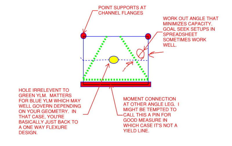
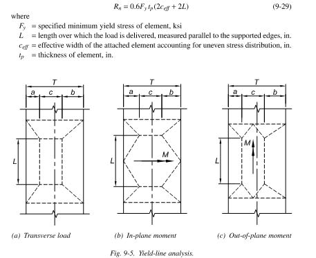
As for the angle bending, the 19mm plate is a great benefit to the yield line analysis as it pushes the yield lines closer towards the supports (which is good thing). In terms of bending, the 19mm plate should only be viewed as a mechanism to better disperse the load into the 25mm angle leg and as just mentioned, modify the yield line mechanism. The yield line analysis should be solely based on the 25mm angle since (as KootK rightly pointed out), the angle and plate are non-composite.
KootK also correctly addressed another item of concern and that is weld stress non-uniformity at the angle-channel interface. This concept occurs quite frequently in (rectangular) HSS wall design with transverse plates, where the load is naturally attracted to propagate to the welds closer the side walls than at the middle of the connecting face. Effective length parameters are usually employed to combat this. A common effective length (Le) applied is Le = (10/(B/t))x(B) where B is the HSS width (in your case, the channel depth) and t is the wall thickness (in your case, conservatively the channel web thickness)(for obvious reasons, Le cannot be greater than B). For tension scenarios, this effective length is what should be used in determining a suitable weld size as well as ensuring the angle thickness is adequate based on the weld size required. For compression scenarios, you could develop the weld for this force or rely on contact bearing if properly fabricated.
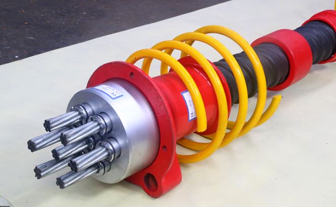
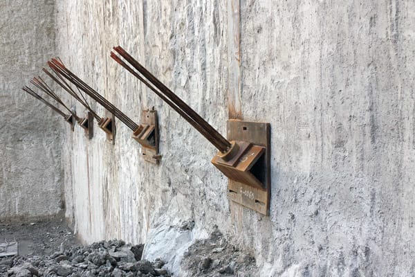
Clearly the intent of the channel is to provide a flat surface of which to affix the 203x203x25 angle, but is this detail also necessary to provide minimum clearance to install the nut between the angle and pipe? I have to say that with the geometry selected, there is compounding inefficiencies that may make eliminating the channel a more suitable approach (i.e. weld the angle directly to the pipe). Yes, the angle would need to be profiled to fit the pipe, but for the fact that the angle may already need to be prepared to properly mate with the channel (assuming the detail you showed is correct and the toes are bevelled to accept fillet welds), can't you go one step further and profile the legs to fit the pipe directly? The extra welding saved (as the welds would now be much more efficiently utilized...angle-to-pipe directly) should likely more than offset the profiling operation. If the pipe is in fact concrete-filled (I completely missed seeing that in the sketch), and the system is compression only, there isn't as great of a concern of pipe limit states being violated, and thus trying to disperse the load over a larger region into the pipe may not be warranted. If nut installation is an issue, why not go with a L254x254x25 or even a L305x305x25 and cut down the legs to what works? The yield line analysis still needs to be conducted in my opinion, but it will vastly simplify the design and eliminate the "keep me up at night" variables that plague some of our minds when dealing with connections that are out of our comfort zone.