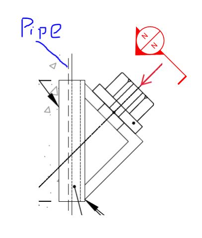
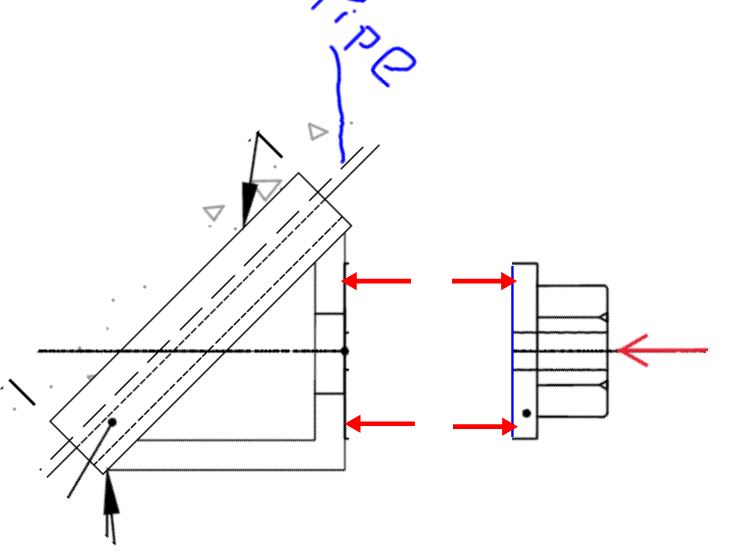
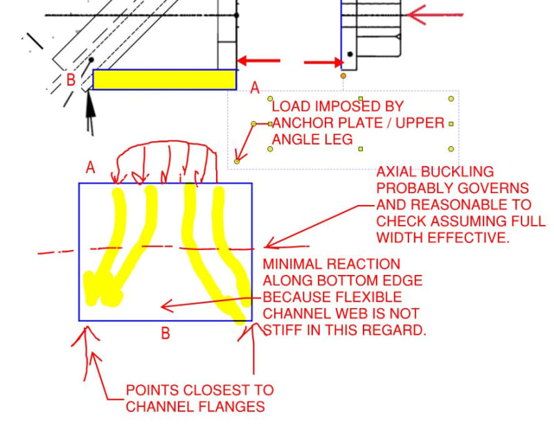
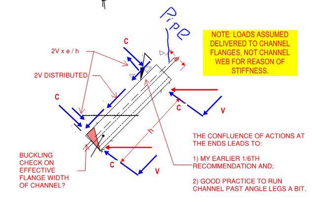
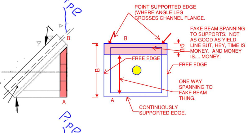
For checking of the leg bending, you would likely want to employ a yield line analysis. As a work-around, you could use Fig 9-5(a) of the AISC Manual paired with Eq. 9-30 and a Qf=1.0. In Fig. 9-5, the 'L' term could be assigned as either zero or the diameter of the hole in the angle leg (that choice comes down to designer preference typically). A simplified analysis of the cable-connected leg of the angle would assume the toe and heel of the angle act as the 'supports' which are assumed to act as pins (again, keeping this analysis simple). Therefore the maximum moment occurring in the cable-connected leg would therefore be 4(Pu)/L_leg where Pu is the force and L_leg is the dimension between supports (i.e. the angle leg length). Comparing this moment against the weak axis resistance of the cable connected leg (phi)((L_angle x t^2)/4)(Fy) where L_angle is the length of angle, t the angle thickness, may lead you to require a thicker angle or a longer angle to properly develop the bending moment. Hence, yield line analysis is what I would recommend to make the design as economical as possible. Further supporting the yield line route, rationally thinking, at some point increasing the length of the angle for greater bending capacity (rather than increasing thickness) would no longer be beneficially as it wouldn't capture the actually failure mechanism forming in the angle. Punching shear is also something that should be checked.
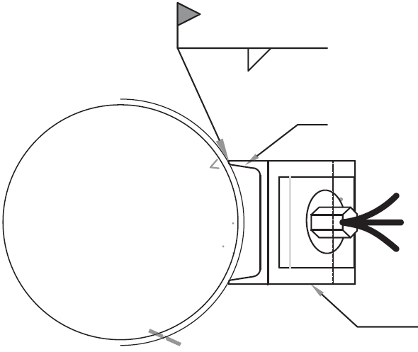
Regarding minimum distance, sounds as though it may be based on the weld length required to develop the load as it transfers from angle to channel (and enough to ensure the pipe wall don't fail any applicable limit states). If limit states are satisfied, a good starting point might be by applying a 2.5:1 force dispersion rate - therefore the minimum distance beyond the angle could be 2.5 x channel flange width.
To your point regarding the use of table 8-4:
"I thought that is what table 8-4 of AISC effectively does since the horizontal component of the inclined force won't have a moment anyways"
This is only true if the horizontal component is assumed to act through the center of gravity of the weld group. If it acts at some offset distance, the horizontal force may either be beneficial to counteract the moment induced from the vertical component or it may be additive to the moment induced from the vertical component (the direction that the horizontal component acts will indicate which condition you have). Drawing a FBD really helps to clarify this concept.

