Continue to Site

Eng-Tips is the largest engineering community on the Internet

Intelligent Work Forums for Engineering Professionals

  • Congratulations KootK on being selected by the Eng-Tips community for having the most helpful posts in the forums last week. Way to Go!

Double dimensioning, illegal, redundant, correct or other

Status
Not open for further replies.

aniiben

Mechanical
May 9, 2017
165
A part similar to the one shown ASME Y14.8-2009 Fig 4-9 (page 28). (Casting Standard)

The one and important difference is that there is an “as –cast” hole thru the part that is not used as a datum feature on the machined drawing.

On the machined drawing: Casting datums and machined datums are shown similar to the datum scheme above. The hole in question (again, as–cast hole/feature) is dimensioned and toleranced from the casting datums and ALSO from the machining datums.

Pos 0.8(MMC) Z, Y, X
Pos 0.25 A, B, C

Z, Y, X- casting datum targets
A, B, C machined datums


Some design/product engineers are seeing this as double dimensioning, others as illegal or redundant and others are just in agreement with this scheme.

The intent is to avoid the “as-cast” hole/feature to be out of “functional specification” before the part is used in the assembly. Since the hole is “as-cast” and does not get machined Z, Y X datum scheme is needed, but deformation of the part during the removal of the material has also been noticed.

I have no much experience with casting and plastic parts, but learning…..

On Tec-Ease I’ve seen a similar example, but again, no “as-cast” hole / feature dimensioned from the casting datums and also from the machined datums (except the initial datum targets that are shown and described /become on the drawing machined datums feature). See attachment for Tec-Ease example.

On Tec-Ease example, lets say Ø15 holes is "as-cast" and is also dimensioned WRT to Z, y and X in addition the the current position Ø 0.4 to A, B(M) and C(M) shown. How you you see it? Double dimensioning, illegal (per the standard), redundant, correct or other?
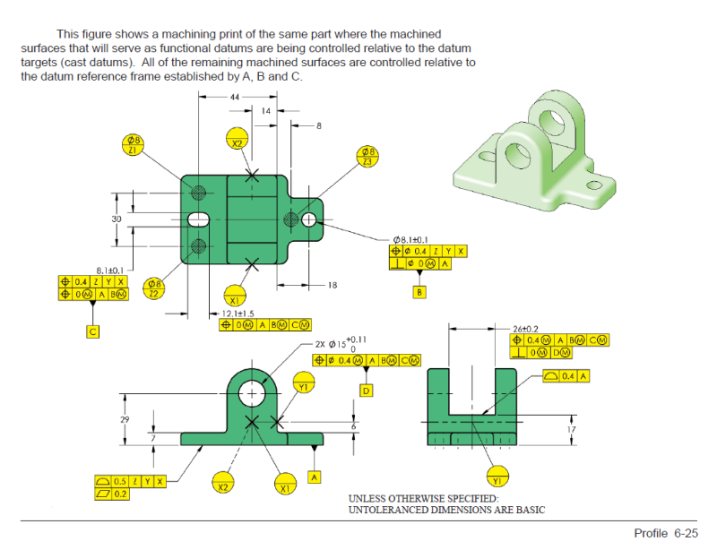
Capture_Casting_page_2_ochn3a.png
 
Replies continue below

Recommended for you

Hi, aniiben:

Per ASME Y14.8, there are 3 methods to present drawings for cast item, namely:
1. Separate view drawing method;
2. Combined view drawing method;
3. End item drawing method.

Fig. 4-9 on ASME Y14.8 shows a 2nd drawing for machining features using "Separate view drawing method". The first would be a drawing for the as-cast item which Fig. 4-9 does not show it. As-cast item will be "material" to make the machined item.

The print does not tell you (and is not supposed to tell you) if this item is casted or machine. If you cast this item and can meet its requirements, then you don't need to machine it.

To answer your questions, the hole (labelled as datum feature B) and the slot (labelled as datum feature C) are machined here. Datum features X, Y, and Z are by default datum features on cast item, while datum features A, B, and C are for machined features. I think you are hung by this statement, i.e., the width dimension 8.1±0.1 is shown from both “casting” and “machining” datums. These two features (hole and slot) are located to datum Z, Y, and X. Datum A and B are merely there for qualification purpose. It basically tell us that machined datums A, B, and C need to be machined on a single setup. It is a qualification process of datum features to make sure they are of quality datums.

Best regards,

Alex
 
jassco,

Well, I am also hung by the fact that the length of the slot (10±1.5) (again the length and NOT the width) is shown / defined based ONLY on the casting datums.

I understand the definition of the machined datums (specially datum feature B=the hole-and datum feature C=the width of the slot), but the length of the slot remains unclear (at least in my mind).

Since it is shown from the casting datums ONLY, should I conclude that will be “as-cast” (same it is shown in my application)? Yes, no, maybe? If no, why not?

Thank you again for your patience
 
Hi, aniiben:

The slot is a machined feature. How do I know that? Because dimensions and tolerances for this feature is on this print for machining (Fig. 4-9). Otherwise, they will be placed on another print for as-cast part which will be "material" for this as-machined part (Fig. 4-9).

The print basically tells you to machine A, B, and C in reference to X, Y, and Z (with a single setup).

Best regards,

Alex
 
Jassco,
Okay. I understood. Thank you very much.
Then the follow up question is why the length of the slot is defined in the standard only based on the casting datums (Z, Y and X) and not based on the machining datums A, B and C?
What could be a good reason to have this kind of example in the standard which suppose to be "the letter of the law" ?
 
The drawing is set up this way because the length of the slot is not used as a datum reference so only a coarse orientation and location relative to ZYX is required. The slot length location in the ZYX reference frame is sufficient for the intended purpose.

The width is given a coarse location and orientation relative to ZYX and then a refinement in location and orientation relative to AB.

The slot is not a cast slot. It is only controlled from cast features.
 
Hi, aniiben:

Nothing wrong with Fig. 4-9 on ASME Y14.8. The issue is how you understand it.

First of all, you need to understand that position tolerance of "tp 0.5 MMC | Z | Y | X " does not refer to slot length but rather center plane (a derived medium plane, technically using Y14.5 language) of the slot in vertical direction. 10.5+/-1.5 is just an FOS (feature of size) which is not supposed to have datums.

Design intents of this part dictate that the hole (8.1+/-0.1), the slot (10+/-1.5) x (8.1+/-0.1), and datum feature A are made in reference of datum features Z, Y, and X. Therefore, datum features Z, Y, and X are used.

If you make the derived medium plane of the slot (10+/-1.5) reference to datum features A, B, and C, it is essentially like a dog traces its own tail, as this derived medium plane is part of the slot itself. In another word, position of slot is created by the slot.

Is it OK to use "tp 0.5 MMC | A | B | C| " for length of the slot instead of "tp 0.5 MMC | Z | Y | X "? Yes, but not elegantly. I think John-Paul Belanger or Evan Janeshewski have better qualifications to answer this question than I do.

Best regards,

Alex
 
CWB1,

I am not confusing datums with surfaces. When I say "datum feature A", I am referring the surface which OP said is created by machining. How can the corresponding datum exist before this machining takes place?

Regardless, dimensional requirements applied to the raw casting do not apply to the finished part. Part deformation due to material removal, among other things, can cause drastic changes in geometry. If this is not controlled by requirements applied to the finished part, then the only option is to rely on the process. Good luck getting a foundry to guarantee their castings will exhibit a controlled amount of deformation when machined.


greenimi,

Your calculation resulting in diameter 5.8 appears to be based on perfectly cylindrical holes. It is probably more realistic, but not truly the worst case for RFS position error.

In this case it doesn't matter much matter which result is used since both are drastically larger than the finished part position requirement of diameter 0.25 RFS.


aniiben,

The slot (with width as datum feature C) in Fig. 4-9 is almost certainly intended to be machined. However, that does not mean it would be impossible to produce it by casting, even if datum features A and B were machined. An actual drawing may have requirements that rule this out, but none were included in the figure.


pylfrm
 
I think (but I might be wrong in my assumption so, please, feel free to correct me) that the casting standard shows casting datum features on the length of the slot 10±1.5 (again, on the machining drawing and on a machined feature) to enforce that COULD be an acceptable (read standardized/ acceptable/ agreeable) option.

Obviously, to show machined datums A, B and C for the same feature (length 10±1.5) is acceptable and fully agreed by Y14.5, so no need to be shown on Y14.8 again.
But, probably the committee wanted to emphasize that showing casting datums on a machined drawing (and the applicable features where those casting datums are shown , are NOT machined datum features) is an accepted option/ in fully agreement with the casting Y14.8 standard.

Interestingly enough, in Y14.8-1996 machining datum reference frame (4.4) wording has the word “should”, which is kept in Y14.8-2009 with one additional sentence added:

“The initial datum targets shall be shown and described on the drawing showing the machined features. See Fig. 4-9.”

The location of the length of the slot from (the casting datums) stayed unchanged.

So, again, I guess (unless I am missing something) that is a valid option (even does not looks like the most logical one).
 
Status
Not open for further replies.

Part and Inventory Search

Sponsor