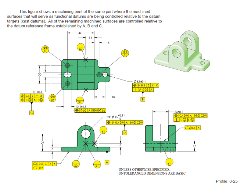
A part similar to the one shown ASME Y14.8-2009 Fig 4-9 (page 28). (Casting Standard)
The one and important difference is that there is an “as –cast” hole thru the part that is not used as a datum feature on the machined drawing.
On the machined drawing: Casting datums and machined datums are shown similar to the datum scheme above. The hole in question (again, as–cast hole/feature) is dimensioned and toleranced from the casting datums and ALSO from the machining datums.
Pos 0.8(MMC) Z, Y, X
Pos 0.25 A, B, C
Z, Y, X- casting datum targets
A, B, C machined datums
Some design/product engineers are seeing this as double dimensioning, others as illegal or redundant and others are just in agreement with this scheme.
The intent is to avoid the “as-cast” hole/feature to be out of “functional specification” before the part is used in the assembly. Since the hole is “as-cast” and does not get machined Z, Y X datum scheme is needed, but deformation of the part during the removal of the material has also been noticed.
I have no much experience with casting and plastic parts, but learning…..
On Tec-Ease I’ve seen a similar example, but again, no “as-cast” hole / feature dimensioned from the casting datums and also from the machined datums (except the initial datum targets that are shown and described /become on the drawing machined datums feature). See attachment for Tec-Ease example.
On Tec-Ease example, lets say Ø15 holes is "as-cast" and is also dimensioned WRT to Z, y and X in addition the the current position Ø 0.4 to A, B(M) and C(M) shown. How you you see it? Double dimensioning, illegal (per the standard), redundant, correct or other?


![[bigears] [bigears] [bigears]](/data/assets/smilies/bigears.gif)