Continue to Site

Eng-Tips is the largest engineering community on the Internet

Intelligent Work Forums for Engineering Professionals

  • Congratulations KootK on being selected by the Eng-Tips community for having the most helpful posts in the forums last week. Way to Go!

Double dimensioning, illegal, redundant, correct or other

Status
Not open for further replies.

aniiben

Mechanical
May 9, 2017
165
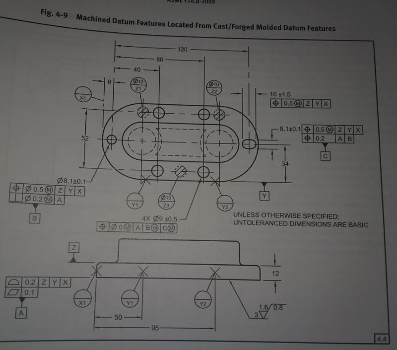
A part similar to the one shown ASME Y14.8-2009 Fig 4-9 (page 28). (Casting Standard)

The one and important difference is that there is an “as –cast” hole thru the part that is not used as a datum feature on the machined drawing.

On the machined drawing: Casting datums and machined datums are shown similar to the datum scheme above. The hole in question (again, as–cast hole/feature) is dimensioned and toleranced from the casting datums and ALSO from the machining datums.

Pos 0.8(MMC) Z, Y, X
Pos 0.25 A, B, C

Z, Y, X- casting datum targets
A, B, C machined datums


Some design/product engineers are seeing this as double dimensioning, others as illegal or redundant and others are just in agreement with this scheme.

The intent is to avoid the “as-cast” hole/feature to be out of “functional specification” before the part is used in the assembly. Since the hole is “as-cast” and does not get machined Z, Y X datum scheme is needed, but deformation of the part during the removal of the material has also been noticed.

I have no much experience with casting and plastic parts, but learning…..

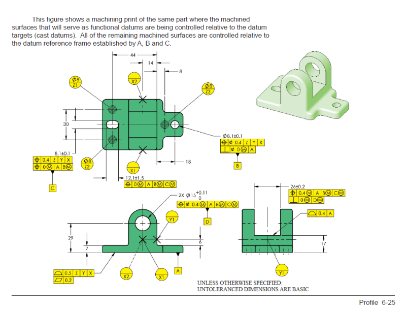
On Tec-Ease I’ve seen a similar example, but again, no “as-cast” hole / feature dimensioned from the casting datums and also from the machined datums (except the initial datum targets that are shown and described /become on the drawing machined datums feature). See attachment for Tec-Ease example.

On Tec-Ease example, lets say Ø15 holes is "as-cast" and is also dimensioned WRT to Z, y and X in addition the the current position Ø 0.4 to A, B(M) and C(M) shown. How you you see it? Double dimensioning, illegal (per the standard), redundant, correct or other?

Capture_Casting_page_2_ochn3a.png
 
Replies continue below

Recommended for you

Here is Fig 4.9 from the Casting standard for reference
Capture_Casting_standard_idf2fi.png
 
There's a statement that dimensions and tolerances only apply at the drawing level they are detailed on. It should not matter if the same dimensions and tolerances are seemingly repeated because the casting acceptance is independent of the machining acceptance.

Some will complain that there's no specific machining operation and therefore the machinists should not get dinged if the cast feature is out of tolerance. If there's any sense to it they would not be and failing the part at any level should have a correct failure analysis.

There are others who point out that if the feature is that critical that it needs to be inspected that it should be machined and not left to drift up from a lower fabrication level.

I would only do this if the lower level feature was used as a datum reference and the dimensions and tolerances were needed to establish the datum.
 
The main question is how to avoid the perpetual blame between the departments:

The holes/features were good when the casting has been delivered/measured versus we didn’t touch the holes/features?

Is this a potential solution?
Looks like the agreement is not achieved yet.

What other solutions, from your experience, could be used? What else could be done to not spend much $$$ in lengthy debates an unproductive discussions ?

Again, I am looking for peoples experience in this area of expertise.
 
3DDave,

Is the OP question and "additional" requirement for an unmachined/ as-cast features
(aka.a. Pos 0.8(MMC) Z, Y, X
Pos 0.25 A, B, C

Z, Y, X- casting datum targets
A, B, C machined datums)

more like a CYA?

 
Per Don Day's article: "Geometric Dimensioning and Tolerancing, The Common Thread of a Multifunctional Design Team"

"If the casting did not clean up, they would blame the foundry for not providing sufficient material as a machining allowance. The foundry in turn would blame the machinist for not aligning the casting properly on his machine tool."

That is exactly what's happening almost every shipment ........... I would also add the stress in the part and distorsion induced by the tooling and fixturing.

Not sure myself how to circumvent that.
 
aniiben:

We buy small quantities of "large" castings (#3,000+ for hydro electric components. All (final) features are located relative to a datum axis. The datum feature is machined in first machining operation. The part is designed in 3D and has a model. We used a portable CMM (laser tracker or arm) and scan the all surfaces of the casting to create a point cloud. The CMM software, using the 3D model, does a best-fit of the point-loud to the model. This immediately tells us if there is insufficient machining stock in any area. It also identifies the locations of the lathe centers that establish the setup for the first machining operation that creates datum feature (datum axis). Hope this helps.

Certified Sr. GD&T Professional
 
Hi, aniiben:

"The hole in question (again, as–cast hole/feature) is dimensioned and toleranced from the casting datums."

This is ok.

"and ALSO from the machining datums."

This is not ok as machined datums did not exist on as-cast.

I agree that "Some design/product engineers are seeing this as double dimensioning, others as illegal or redundant".

You need to draw a very thick line between as-cast and as-machined.

Best regards,

Alex
 
References flow up the print structure, never down, so cast features cannot be driven by dimensions in a machining print. Regarding the holes, if you want them to remain as-cast then do not detail them on a machining print as doing so is calling for a bored hole.
 
References flow up the print structure, never down
So if we're designing an airplane, we would assign tolerances to each itty bitty part based on the requirements of each at that level?
Good luck getting the plane to fit together. [smile]


John-Paul Belanger
Certified Sr. GD&T Professional
Geometric Learning Systems
 
Hi, Belanger:

CWB1's statement is accurate. References flow up the print structure, never down. If there is a feature that you are not sure, you can leave it to its parent component or assembly where the component is used. It does not matter whether you design a plane or a watch. The process is universal.

Best regards,

Alex
 
Let me clarify my point. The way to design large assemblies is a combination of bottom-up and top-down, in terms of tolerancing.

I do agree with his point that an "as-cast" hole generally shouldn't be detailed on a machined print as that might imply machining it to that size. But I was getting more at the dimensioning and tolerancing layout, not the actual manufacturing specifications. (And the purpose of a print is dim/tol layout, NOT manufacturing specs, per paragraph 1.4(e) of the Y14.5 standard.)

My bit about the airplane had to do with the tolerance stack-up effect that occurs if we focus too much on the path of "flowing up." Trust me, an aircraft can't be built if we examine the tolerances from a detail level only. I don't think that CWB1 was saying anything about tolerance stacks, but I was just cautioning against relying too much on a one-way flow of things.


John-Paul Belanger
Certified Sr. GD&T Professional
Geometric Learning Systems
 
aniiben,

The "machined drawing" is serving as the finished part drawing, correct? If so, and if there is a corresponding functional requirement, I'd say it's perfectly reasonable to apply a tolerance to a cast feature that references a machined datum feature. Ideally, the casting drawing would have a tighter tolerance for that same feature, referencing cast datum features that will eventually be used to establish the relationship between the casting and the machined datum features.

I don't understand the purpose of the 0.8(M) position tolerance that is applied to the same feature but references the cast datum features on the "machined drawing". Is that intended to cover some separate functional requirement of the finished part?

If you have some strange drawing structure where dimensional requirements on the casting drawing somehow apply to the finished (machined) part, then much of what I said above may not apply. I've never come across such a scheme.


If I am designing a part that I intend to be manufacturable by casting and subsequent machining, I will generally design the finished part first. Based on that finished part design and the details of the planned manufacturing process, someone (who may or may not be me) will then design the casting.

Wherever practical, I'd recommend the finished part drawing allow machining on features that are generally intended to be cast. This keeps options open for manufacturing.


pylfrm
 
pylfrm said:
” The "machined drawing" is serving as the finished part drawing, correct?

Yes, correct.

pylfrm said:
“I don't understand the purpose of the 0.8(M) position tolerance that is applied to the same feature but references the cast datum features on the "machined drawing".

Has been decided (long before my time) that due to some economic reasons some holes/ features to be manufactured “as-cast”. (was good enough)
Then, if they were “as-cast” the decision has been made to have them toleranced from the “as-cast” datums (again, on the machining drawing). The main argument was: manufacturing is not touching them and has no intent to change their size/ location/ orientation/form. Again, “no intent”...........

Well, all was good until after the machining process has been noticed that these “as-cast” holes and features are no longer where they need to be, based on the casting datums (Z, Y and X).
Solution: Another ECN has been run and a positional callout (for the holes) has been added on the machining drawing with tighter tolerance from the machined datums A,B and C. And the argument was the deflection of the part during manufacturing. (please note that the position from the casting DRF was not removed or changed)

To show the “as-cast” holes on the machining drawing is legal (I guess) because the casting datums are (already) shown on the machining drawing (that is a standard requirement), pretty much in the same way as it is shown in the standard and also on Tec-Ease example embedded (casting DRF’s are on machining drawing).

Now, as I stated before, some will consider this approach “double dimensioning”.........(same as the title on the thread)
 
No, this is worse than “double dimensioning”. One should not put a dimension with tolerances on a print that no one is going to use it.

Best regards,

Alex
 
Belanger, if I am understanding correctly then yes I agree, designers and draftsmen may need to refer to higher level prints to determine available space claim and consider their parts total stackup during print creation. However, end-users of those prints should only have to look down, not up for necessary references. Tradesman often only have access to prints below their manufacturing level in the structure. In this case a machinist likely would have access to both the machined and casting prints, the foundry OTOH would only likely have access to the casting print.

JMO but if after machining a cast feature is suddenly out of spec then I'd doublecheck the tolerance stackup between both prints in search of a fundamental error. On the OP's machined print I'd never dimension an as-cast surface however I would use a note to clarify that its to be left as-cast and unimportant as anything other than background geometry.
 
aniiben said:
Then, if they were “as-cast” the decision has been made to have them toleranced from the “as-cast” datums (again, on the machining drawing). The main argument was: manufacturing is not touching them and has no intent to change their size/ location/ orientation/form.

It sounds like this tolerance probably does not reflect any functional requirement of the finished part. If so, I'd say the tolerance should be eliminated. Do you agree?

What diameter tolerance is applied to the hole on each of the two drawings?

What position tolerances are applied to the hole on the casting drawing? What datum feature references are used, and how do they relate to those used on the finished part drawing?

Does the machining process use datum features X, Y, and Z (as defined on the finished part drawing) to establish the relationship between the casting and the machined datum features? If some other method is used, please explain.


pylfrm
 
Pylfrm,

See the sketch for "conceptually" the same part as the one in question.

Here are the answers for your questions:

Imagine fig 4-9 (14.8-2009) but the part is round (not oval shape)
Datum target Z (3) as shown on the face of the part.
Datum target Y the OD
Datum target a width of a slot.

Blue holes” as cast”
Same size tolerance applied on each hole on each of the two drawings (casting and machining)
Positional tolerance on the machining drawing
Pos Ø 0.8(MMC) Z, Y, X
Pos Ø 0.25 A, B, C

Positional tolerance on the casting drawing
Pos Ø 0.8(MMC) Z, Y, X
 
 http://files.engineering.com/getfile.aspx?folder=d09ebf9c-e0b0-420b-867f-2ace5895e2ad&file=Capture_Casting.png
aniiben,

You skipped the first and last questions.

It seems quite strange that the holes have a size tolerance of 5, but a position tolerance of 0.25 RFS. What's the story there?


pylfrm
 
Hi, aniiben:

Are you aware that there is something wrong with the follow statement?

"Same size tolerance applied on each hole on each of the two drawings (casting and machining)."

The blue holes are not created on the machining drawing, therefore they should not have positional tolerances. If you really want, you may add reference dimensions.

No dimension with tolerance may appear more than once for any given feature.

Best regards,

Alex
 
Status
Not open for further replies.

Part and Inventory Search

Sponsor