Continue to Site

Eng-Tips is the largest engineering community on the Internet

Intelligent Work Forums for Engineering Professionals

  • Congratulations KootK on being selected by the Eng-Tips community for having the most helpful posts in the forums last week. Way to Go!

Double Angle Connection with Torsion 1

Status
Not open for further replies.

RFreund

Structural
Aug 14, 2010
1,885
I'd like to bring this question back up:

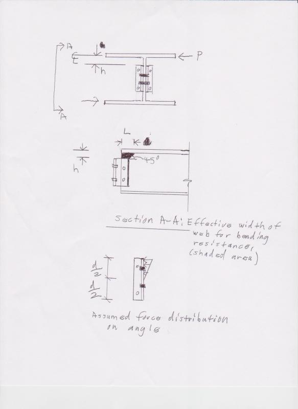
I'm trying to get a list of checks for this situation. Especially for the beam web and double angles.

For the beam web, can you simply add shear stress plus torsional shear stress?
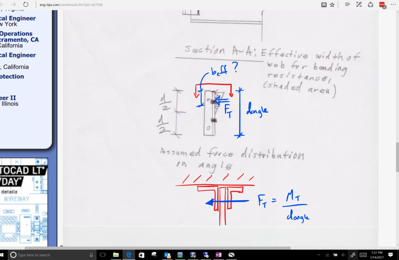
For the double angles - BA suggests a T/C couple and checking strong axis moment, but this sees odd to me as the angle is fastened to a support and you would probably get a significant amount of capacity. Checking the legs as tall thin rectangles in torsion seems pretty conservative. Breaking the torsion up into a T/C couple as M/(L.angle/2), then checking half the angle as "flange bending" seems like a possibility but also kinda odd.

Any thoughts?

Thanks in advance!

EIT
 
Replies continue below

Recommended for you

Some years back I did a in-depth study on this using FEA......what I found was: such a connection is severely limited by bending in the web (of the beam developing the torsion). Basically, the beam transfers the torsion by a couple that is perpendicular to the web. In order for it to get to the angles.....a bending moment is developed that is a cantilever from the center line of the flange to the top of the angle connections. (I got identical numbers by cantilevering the force and assuming the width of the web that resists it was about equal to the depth of the angles.) You can check the angles like a seated beam for the force at that point, but it's a moot point because the web typically doesn't make it.

Ergo, you can't use this type of connection to transfer any significant torque. You have to either: change the connection type or you need to have beams framing into the torqued beam (on each side of the torque) and take it out that way. (Which you can do even with a simple shear connection. You just have to model it with a (flexural) fixity of maybe 10%.)
 
@WARose - great input. Thank you!
In my case the beam web is pretty thick (>1"). But the angles are not (5/16"). Any suggestions on the effective width of the angle?

Thanks again.

EIT
 
Any suggestions on the effective width of the angle?

Assuming you are talking about the force distribution (from the force perpendicular to the angles)......I typically assume a triangular distributed load. (See pic below.)

By the way, if you run with this, keep in mind (for the "stick" model): the end torsional fixity isn't going to be 100% fixed or free. Estimating that is important to determine rotation. In the study I mentioned in my first post, I typically got conservative (i.e. higher than theoretical) rotations by releasing just 10% of the fixity. However, that probably will vary from beam to beam based on web stiffness.

By the way, in my pic, I don't show a cope.....if you've got one....you've got issues trying to get this out of the beam.

"
Torsion.dist_001_t5qjtx.jpg
 
Thanks this is helpful.
Regarding the angle -
I was talking about the force perpendicular to the web applied to the outstanding leg of the angle. I was thinking about checking the outstanding leg in bending. I was only thinking about using an effective width equal to the length of the out standing leg.

Torsion_-_Double_Angle_-_Leg_Bending_fyflwu.png


EIT
 
I was talking about the force perpendicular to the web applied to the outstanding leg of the angle. I was thinking about checking the outstanding leg in bending. I was only thinking about using an effective width equal to the length of the out standing leg.

To go with your mark-up....I'd take "beff" to be "d/2" (my notation; i.e. half the angle depth of one angle).....with the load distributed as I show it.
 
Status
Not open for further replies.

Part and Inventory Search

Sponsor