@saplanti
First of all Greetings from my end!
")
Secondly thank you for commenting with your concern on this thread. its really constructive and get more interesting when we got interaction with some different cultural and mind set personnel round the globe.
Eng-tip is quite means alot to me and always welcoming to share their thoughts , experience, lesson learnt and much more.
DONT BE STATUS QUO and judging to anybody without any information about him, every one is here to discuss the technical points and obviously we are here for some reason. For your information, I've been working since 15 year as mechanical design engineer of static equipment and I'm graduate certified engineer.
Now lets come to your first points,
1 - "I do not understand how these things work as you described. Is there any purpose doing the assembly like that? I would normally expect that the pump suction is connected onto the nozzle by flange or weld. The nozzle was supposed to have an insert into the vessel for the suction assembly with elbow in accordance with Hydraulic Institute standards on the vertical pressure vessels."
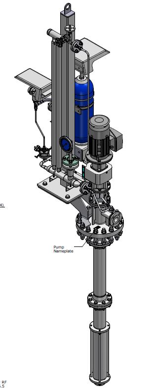
Staticmh reply: First you understand the assembly requirement and constraints, for the horizontal vessel (especially in sump drain drums) whether with boot in concrete pit or buried condition pump assembly is require for the successful suction of the sludge contamination through submersible assembly inside the vessel (boot).
See below image of pump assembly (Isometric view) [FIGURE-1]:
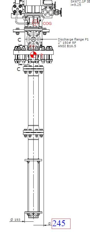
Similarly now see the maximum dimension of the submersible part of pump assembly, which is marked by vendor as 245mm and understand that is the limit for us to maintain the inside diameter of the nozzle. the nozzle inside diameter should be within the range of 245mm to easily insert the pump submersible assembly through nozzle pipe.
See below (blue color limit dimension) [FIGURE-2]:
But unfortunately our procurement people bought it wrongly as Schedule-80, even it was clearly mentioned on drawing to procure the schedule-60, Anyway the mistake done and being an engineer we have to solve it.
The reason why we recommended the schedule-60 was the clear gap maintain for the ease of insert the pump assy. through pipe inside.
Received pipe = NPS-10" ; schedule - 80 and ID is 242.82mm
Required Pipe = NPS-10" ; schedule - 60 and ID is 247.6mm
(Pump assy. maximum limit. is 245mm)
with NPS-10" pipe schedule - 60 , 247.6mm - 245mm = 2.6mm gap is available which is sufficient for insert through nozzle pipe.
But we have now NPS-10 , schedule-80, so it will be like that 242.82 - 245 = -2.18 mean pump cant be insert through the nozzle pipe inside diameter due to lesser diameter of pipe. now due to not having other option we intent to machine the pipe from inside to maintain the equivalent I.D of schedule-60. (i.e. 247.6mm)
My main concern of query was to get the advice and endorsement on my intention of solution (that is machine the pipe inside), now share your concurrence whether ASME SEC VIII Div. 1 allow to machine the pipe or not.
Be noted the vessel is U-Stamped and we can not do at our own, ASME Inspector intervention is requested already but response is awaited, meanwhile i thought to discuss with my eng-tip family that is anybody can advice on my case or anybody earlier had solved the same problem which i am facing now.
Now lets come to second points,
2-
"You say that the suction elbow pipe assy will go through the blind flange. This kind of assy will cause more problems, especially vibrations in the suction line, and blind flange connection and on the weld on the blind flange will suffer. To cut the problems you may need to weld the suction pipe close to the suction area by support members on the vessel bottom wall in the vessel as well. I am assuming that you are not the vessel manufacturer, but the installer of the equipment."
Staticmh reply: Clear your understanding that there is not any elbow involve neither in my above post and nor any where else, only the flange assy. word used which is shown above in figure-1. Pump loading received from pump vendor and already verified the calculation in WRC / FEA at shell to nozzle junction. we're the vessel manufacturer & its EPC contractor and additionally own the U1 , U2 & R stamp. Only the pump is sourced out from some specialized vendor.
Now lets come to third points,
3- "
It seems that there is a mismanagement issue here. I suggest you discuss the issue first with the process engineer, second with the design engineer of the pressure vessel on the application."
Staticmh reply: There is nothing mismanaged all the things are self explanatary and for your kind information, you need to understand the case as above depicted fully with as supportive images and explanation. And there is not any process engineer involvement require to fix this up its purely mechanical discipline clarification & case. You should understand it if you have any bit experience of static equipment design.
Hopefully all the things are clear to you and got the answer of each point wise.
Thanks!