Continue to Site

Eng-Tips is the largest engineering community on the Internet

Intelligent Work Forums for Engineering Professionals

  • Congratulations waross on being selected by the Eng-Tips community for having the most helpful posts in the forums last week. Way to Go!

Does a spherical diamter position require rotation dof to be locked down

Status
Not open for further replies.

sendithard

Industrial
Aug 26, 2021
186
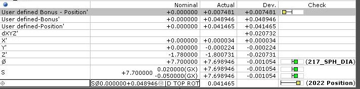
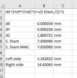
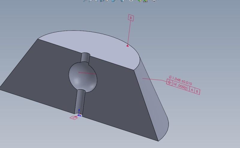
Is the below valid without locking down rotation so you have a plane to measure distance from x and/or y distance from?

The datum cylinder A defines X & Y in location and datum plane B defines the true position distance of the sphere below said plane. So in theory you can garnish a radial deviation from this true position in space, but what you can't do is define said deviation from a X and Y plane. So you have your overall deviation, but it can't be quantified with the typical X & Y deviation. Therefore, I'm wondering if this particular callout is valid b/c the rotation isn't locked down via a tertiary datum ref frame.

Thanks.

spherical_crkews.jpg
 
Replies continue below

Recommended for you

It's a sphere - it hasn't got a way to measure rotation.

It's acceptance is that dX^2 + dY^2 + dZ^2 <= (S Dia./2)^2 at MMC.
 
sendithard,

I agree with 3DDave, the position tolerance is fine. There is no need for a tertiary datum feature in this case.

Just to stir the pot, I would also say that it would have been fine with just the A reference (if all you cared about was the centering relative to the hole and not the distance from the planar face).

Evan Janeshewski

Axymetrix Quality Engineering Inc.
 
Thanks...appreciate the comments.

I think I'm basically going to lock the rotation down so I can output X and Y location from a frame of reference for the machinists. I agree the sphere can spin freely, but knowing what offsets to make helps. I just don't have enough experience to understand if that was valid given you can't output XY dev without a frame of reference.

Thanks again.
 
Dave,

How would you get the dX and dY numbers in your above equation without defining some reference frame? I agree you don't need to stop rotation, but it seems to me you need to define some approach.

you posted an equation above, I'm not sure what you were trying to convey, but the equation I am using is:

sqrt(dX^2+dY^2+dZ^2)*2 <= Sphere diametrical dev from MMC

the bottom calc in the pic is the software's calc, but it forces the use of max inscribed for this feature. I like to be able to use least sq sometimes so you can only do that manually. Hence, I used the equations above to get some numbers.

calcs_bmkeux.jpg
 
3DDave,

I believe in hard gages, the largest pin that can fit in a hole is the hole size. That is a nice cocktail on the beach type scenario.

That said, on a cmm when you hit a 1" deep hole with 3 layers of 7 hits, so 21 hits total, did you find the highs? Can you count on those 21 hits on extrapolating the maximum inscribed hole size? Will this mimic a hard gage? I just got a primary external datum that is a .150" sphere as a primary datum, but the sphere is chopped off and is only 1/3rd complete. So the remaining 66% of the datum is missing. Is this datum surface made for the external highs minimum circumscibed method or perhaps an average method like least squares?

CMM output has utilized least squares for a long time, if a hole requires more stringent analysis, I'm game, I'll hit it will all I got, but it all depends on what the job requires. I deal with CT meshes now as well...that is a whole nother ball game. The mesh you get is not reality, so do you think doing a max inscribed version of an internal sphere is reality, when the mesh you get is not reality anywhay?

Your equation above I think is incorrect. Can you address that?
 
What do you think is incorrect about the equation?

Not much of a sphere if 2/3rds are gone. I expect that the area remaining is far less than 1/3.

I think you understand that least squares pretends the mating will happen within solid material, which is entirely unrealistic.

Up to you to figure out if the feature deformation is so large that missing the high spots renders the measurement invalid.

The CT mesh vertices should lie on the geometry; the edges and faces probably don't. No different than using typical hits with a CMM probe. If you have bad data then nothing will work right.
 
sendithard said:
I'm wondering if this particular callout is valid b/c the rotation isn't locked down via a tertiary datum ref frame

Definitely valid, because you don't always need to stop all 6 DOF.
Generally speaking - sometimes adding another constraint which is not required by the datum references is not wrong; at the worst case, it will result in an over-restrictive evaluation but no bad parts will be accepted. But often it will have no functional implications and can sometimes aid inspection and manufacturing.

In this particular case,
Is the model shown in the image section cut by half to show the hole and internal sphere, or is this the way the actual part looks like (round slot and half-sphere)?
It might be a stupid question, but I ask because,
If the former, then:
1. How is the sphere being produced and inspected?
2. For a part fully symmetrical around the hole's axis, the position deviations in the X and Y directions (those normal to the hole's axis) might be of no use to manufacturing.
 
3DDave,

The sphere primary datum I stated is missing 66% of it's surface area, I used the term 'chopped off' to make it simple. That said...I agree it is a bad datum, but that is the customers demand, and everyone on our end understand this. So we have this poor datum. Using a real life hard gage mathmatical measurement like min circumscibed on an external sphere or any other diametrical feature is notoriously 'unstable' with CMM's when you have less than 180 degrees of surface area...lets just call 180 degress of surface area 50%.

So you can evaluate the diametrically poor primary datum as strict GDT type methodolody using all exterior hit points as 'hopefully' your real highs and get a fluctuating, unrealiable meaaurement routine, or you can use least squares which is more stable and has been used by cmm programming professionals for quite a long time. If the requirement was to never produce a part with interference I would deviate from this(if even this worked on a shit datum), but I'm speaking in general terms....and not to mention you cannot just click the min circum tab on a cmm softare with a shit datum and get a proper result...you would get very bad data sometimes.

If this was a part that was defining whether an airplane could crash, this would need to be measured differently, and by god the datums would need to be proper...but we deal with shit datums and tighter tolerances than I think these parts need.

I don't think your equation makes sense, but you are lightyears ahead of me in knowledge, so I was wanting to see your thoughts on my posted equation vs yours....yours doesn't make sense to me. My numbers posted above are correct.

My equation is:
sqrt(dX^2+dY^2+dZ^2)*2 <= Sphere diametrical dev from MMC

not

dX^2 + dY^2 + dZ^2 <= (S Dia./2)^2 at MMC
 
@Burunduk

I can't post the real part, but although this part looks sectioned this would represent the real case to some degree.

The real part has two flat sides. So, I could use either one, or the midplane to establish y.

If I don't establish a definitive rotation, the machinist doesn't know if the X,Y,or Z is the culprit in the out of tol part. They just get an out of tol value without defining a definitive y plane. So given that we know a part can spin freely for a sphereical feature, how could an engineer let it spin if a machinist wouldn't know if they needed to move x or y on their offsets? So is this an issue of a valid callout, but not valid for real life production value?
 
sendithard,
Since the part is not shown sectioned like I thought it might be, and it's not of pure rotational symmetry, you are correct. The deviations in X and Y are useful for the machinist. For a purely symmetrical part it would be different. In the directions normal to datum axis A, it would be comparable to a situation when both the datum feature and the controlled feature are coaxial diameters. Then of course, there would be no use to separate the coaxiality error offset to X and Y components. The machinist may only care about the off-center axis distance, which is just half the measured value for position (or can be estimated by half the runout measurement if the process is known to produce an accurate form).
 
The reason for the traditional "least squares" was the lack of ability to do the correct thing, not the superior accuracy. It will mislocate where an actual sphere of the calculated diameter would end up. It becomes "stable" by ignoring the actual surface. Perhaps in your case it doesn't matter, but current computers allow the results that a real gauge sphere would produce.

I suppose you measured the surface area in the CAD model - I don't have access to that and it's not a measure that would describe the feature on a drawing.

You might brush up on your algebra. Divide both sides of your equation by two and then square both sides.

You can create a process drawing with whatever datum features you like to explain to the machinists the coordinate system you like.
 
Least squares is not totally unrealistic and not as bad as the average ASME standards user might think. Contact only at the highest points as can be determined in free state may not be the actual assembly condition. Forces acting at assembly with fasteners or other clamping or fixturing methods cause deflections and deformations, and the high points may no longer remain high. Additionally, datum feature simulators mimicking mating surfaces, made to gage tolerances, generally have much less form variation than the surface that the datum feature will mate to at assembly, and this is when concepts such as 3 points of contact become the theory which differs from reality. Some of the mating with an "untrue" counterpart might occur at the low or intermediate points, thus "within" the material. The ASME Y14.5 and related (such as Y14.5.1, Y14.45) standards do not pretend to be able to predict the exact mating condition for every case possible, so they just prescribe high points, minimum circumscribed, maximum inscribed datum feature simulators to establish uniform rules, based on a general initial mating condition, neglecting some unpredictable physical factors - for better or worse.
 
An average user -

"The fitting algorithm that is the default in most CMM software is based on a fundamentally different paradigm than the ASME dimensioning and tolerancing standards. The least squares best fit is optimized more for straightforward and stable computation, as opposed to assessing extremity-based fit with a mating feature. This can result in significant error in measured values for size and location of features."

 
3DDave,
That's an interesting quote, but why don't you credit the author?
Anyway, both paradigms don't describe the physical reality precisely.
"...can result in significant error in measured values" - can indeed, but may not.

When considerable forces act at assembly and/or during the functional application of the part, the mating, especially with the primary datum feature, is most probable to occur somewhere in between the high points and the best fit surface. The main advantage of the extremity based analysis is that it provides the CMM the means to account for the datum precedence order. When 6 degrees of freedom are constrained, if all 3 datums are simulated at best-fit, nothing reflects the datum simulation sequence.
 
The interesting thing is the lack of commitment from you on whether you believe it's from an "average user" or not.
 
That's up to you to tell, because you know whom you quoted.

Regardless, I slightly go back on my previous statement suggesting that extremity points may provide a benefit that fitting methods can't: "The main advantage of the extremity based analysis is that it provides the CMM the means to account for the datum precedence order" is not entirely true. The primary datum could be simulated by the best possible fit. The secondary could be simulated by fitting to the actual feature with the constraint of orientation to the primary datum. The tertiary, if used, would follow the same idea; constrained by fixed orientation and possibly location to the primary and secondary datums, yet fitting as it is able to the actual tertiary datum feature, not necessary to a high point.
 
OK - I got the impression that you felt you knew all about average users
 
Yall have been a blessing to me in my learning curve with GDT and I love these discussions.

All I know is when we get a completely shitty datum, like a 1/2 sphereical datum shit can get all messed up, specially when you use min circumscribed. How can you accept 4 hits on the left side of a sphere as the proper sphere creation? Least squares isn't an avg user thing. It takes one click to change from max inscribed/min circum/lst square, it is a quality decision. If you can't locate a datum right that the customer sent with 40 hits on the left side of a sphere and all parts are failing using strict gdt, do you just quit the game and let the next guy fake it or make the incredibly average decision to toggle the dropdown to lst squares.

3DDave....your equation makes no sense to me....below is your equation piped into excel. It simply doesn't add up, we'd be passing every part made
Capture_utgg83.jpg
 
Status
Not open for further replies.

Part and Inventory Search

Sponsor