Eng-Tips is the largest forum for Engineering Professionals on the Internet.

Members share and learn making Eng-Tips Forums the best source of engineering information on the Internet!

  • Congratulations JStephen on being selected by the Eng-Tips community for having the most helpful posts in the forums last week. Way to Go!

Do you still do load takedowns by hand?

RegularSurround7640

Structural
Joined
Jul 8, 2025
Messages
5
I’m a chartered structural engineer (CEng MICE) in the UK, and over the years I’ve done load path calcs for everything from small houses to big infrastructure and power stations. One thing that’s never really changed: working out vertical loads from 2D plans has always felt awkward and time-consuming, especially early in a project before I commit to an analysis model.

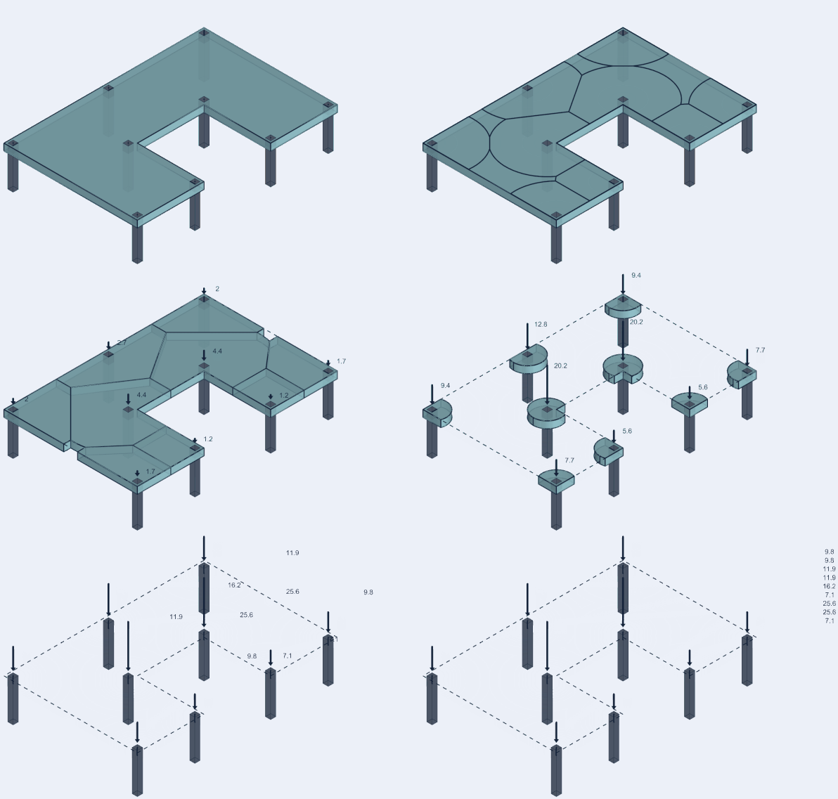
I got tired of feeding wall loads into spreadsheets, and then checking, so I started building a tool to make that quicker and cleaner. It’s web-based and works off PDF plans. Still early days, but it’s working for me.

I’m really curious, how are you all handling this in practice? Still doing it manually? Custom spreadsheets? Something more automated?

And if a tool like this could save time on those early calcs, is it something you'd actually use regularly?

Happy to share the current version if anyone’s interested. Would really appreciate honest thoughts.
 
For me, I imagine this would end up taking longer than hand calcs - unless it was a lot of stories - jobs I typically do not engage in.
 
My perception of load paths only includes determining the paths. It does not include calculations of magnitude. I think of that as "analysis" in whatever form I opt for at the time (handcalcs, spreadsheet, or a computer model). I would be interested in what you are working on.

From a calculation standpoint, I generally computer model my simple structures when needed but only after I am comfortable with my load paths. I started a thread on the Student Discussion board the other day about load paths. I wanted some clarity and consistency in what we all perceive them to mean. Just like here, where we both seem to judge them to be somewhat different things.

I noted many people reviewed that post, but only 2 experienced engineers responded and no student responses. Either it is too simple, not challenging, intimidating or any combination. I have no idea which. But it has been interesting. The request was to create your own description of what a load path is and solve 2 somewhat simple structures but within your description. I was not asking for a set of steps to perform, just where does your answer follow your description and do what your description states.
 
Last edited:
I do load takedowns manually using layers in AutoCAD. I don't love this approach but it's generally simple and relatively efficient for my purposes. For more complicated structures, I'll create a partial or full model in RISA3D.

I saw your post on reddit not too long ago. What you've created looks pretty slick. If I'm understanding the functionality correctly, I think you'll want to add the ability to transfer loads through floors. Also, I would want to be able to represent point loads. Finally, load types and load combinations would also be good.

Overall nice job. Creating something like this is certainly not simple. It's always hard to find the right balance between creating a tool that's so basic it's not of much value versus so complicated that you'll never finish. I can see this as being useful as a quick sanity check of the overall load paths/distribution.
 
I have never heard the term "Load Takedown" but I mainly work alone and in a limited region. It sounds like it is the same as what I call "Load Path".

Are they the same in your opinions?

I looked online and see a lot of info on load takedown. Is it limited to Gravity Loads? I ask because several descriptions said "gravity loads".
 
I have never heard the term "Load Takedown" but I mainly work alone and in a limited region. It sounds like it is the same as what I call "Load Path".
I have no idea what the correct terminology is here. I normally refer to this as "Load Path", but I used "Load Takedown" here because OP used the term. In my mind, it's simply the path that an applied load takes in it's journey through the structure from point of application to the foundation (or other boundary condition).
 
For simple structures (mostly residential) we are still doing this manually. But I'd love to see more of what you have developed, if there's an ability to be more efficient and reduce errors I'm always intrigued.
 
Hand calcs to work out tributary width and floor loading and enter that in the model.
If I'm looking at total loads of a structure I might do that at the start (to give and preliminary estimate) and the end (to sanity check my model output). Again hand calcs. For the type of work I do, going beyond hand calcs really isn't needed.

Another fellow Eng-Tips user briefly popped his head to discuss a similar project. This was the result, seems that he charges $49/month for the tool which for that price I hope it is pretty damn powerful. It also uses the description of "Load takedown" which is a new one for me, but presumably it achieves similar to what you are looking at.


(I received an early beta copy of the software, but I didn't really use it.)

HERE IS THE DISCUSSION FROM 5 YEARS AGO:
 
Last edited:
Thanks for the input, really appreciate it. The biggest challenge throughout has been finding the right balance between keeping it simple and adding enough useful features.

Right now, I’ve deliberately kept things very lean. From my own experience on residential projects, a surprising amount of time still goes into manual spreadsheet work just to do basic gravity load takedown calcs, especially for ground beam loadings and pile loads on multi-plot residential projects, so I figured even a lightweight tool could be a time saver at that stage.

The current workflow is intentionally simple:
  • Load and scale a PDF plan for each floor level and align it using a common project basepoint.
  • Draw walls and floor areas, assign basic properties.
  • As you draw, support conditions and tributary areas update automatically, with visual feedback.
  • On-screen results and summary tables.
  • Export to CSV/XLSX (partially implemented).
That said, I completely agree with the comments about load transfer through floors, point loads, and load combinations. Those are definitely on the roadmap as I think I can add them without disrupting the simplicity of the tool.
 
My perception of load paths only includes determining the paths. It does not include calculations of magnitude. I think of that as "analysis" in whatever form I opt for at the time (handcalcs, spreadsheet, or a computer model). I would be interested in what you are working on.

From a calculation standpoint, I generally computer model my simple structures when needed but only after I am comfortable with my load paths. I started a thread on the Student Discussion board the other day about load paths. I wanted some clarity and consistency in what we all perceive them to mean. Just like here, where we both seem to judge them to be somewhat different things.

I noted many people reviewed that post, but only 2 experienced engineers responded and no student responses. Either it is too simple, not challenging, intimidating or any combination. I have no idea which. But it has been interesting. The request was to create your own description of what a load path is and solve 2 somewhat simple structures but within your description. I was not asking for a set of steps to perform, just where does your answer follow your description and do what your description states.
I have had similar conversations on this before, I think it might be a regional thing in terms of how the terminology is understood and applied in day to day usage. I am used to using load take down or load path calcs to refer to gravity loading assessments, the sort of task you would undertake at an early project stage for complex projects or for finding foundation loads or beam loads for simpler structures.
 
I know it's not the point of the post and I don't want to sound like I'm trying to cause an argument of any kind.. but I believe the term Chartered Structural Engineer is for chartered IStructE members. Chartered ICE members are to use the term Chartered Civil Engineer, even if your specialty is structural.
 
I know it's not the point of the post and I don't want to sound like I'm trying to cause an argument of any kind.. but I believe the term Chartered Structural Engineer is for chartered IStructE members. Chartered ICE members are to use the term Chartered Civil Engineer, even if your specialty is structural.
Yes, there should be a comma.
 
For simple structures (mostly residential) we are still doing this manually. But I'd love to see more of what you have developed, if there's an ability to be more efficient and reduce errors I'm always intrigued.
Thanks, take a look at the beta: https://www.loadtakedown.com

It’s still very much a work in progress, but if you get a chance to try it out, I’d really appreciate any feedback. What works, what doesn’t, and anything you think would make it genuinely useful to you.
 
My definitions:

Load path = the path that the loads take from application to foundation.
Load chase down = the accounting process that tracks loads through the load path.

@RegularSurround7640 , I'd be interested in the tool. I do mostly residential, and since nobody wants walls anymore, much less walls that stack, they're often complicated webs of transfer girders. Doing it by hand is certainly a pain. Tools like Forte help, but often I need to track magnitudes early to do preliminary foundation sizing to coordinate with geotechs or help architects do layouts on the rare occasion they let me drive part of the design for efficiency.
 
The biggest challenge throughout has been finding the right balance between keeping it simple and adding enough useful features.
For me, this has been the single biggest challenge in developing software tools for engineering purposes. If I'm not careful, my tendency seems to be creating something that becomes too complicated, to the point that I either won't have time to finish, or the underlying code folds under the weight of its own complexity.

I once considered creating a tool similar to this, but got stuck when it came to dealing with beams. Should all beams/frames be simply supported (pinned)? If not, then next thing you know you need to define boundary conditions, member stiffnesses, material properties, etc. If you're not careful, you're suddenly trying to recreate RISA3D from scratch. The key is definitely finding the right balance.

It's promising that somebody else created a similar tool and is (presumably) receiving $49/month for it.
 
I don't know if I'm missing something, but why not use FEM software for this? If it's steel or concrete, you could potentially do a ton of design in the software as well. If it's wood or something else, you can get moments and loads. FEM allows for quick changes, removes some guesswork from junior engineers, and is easier to track loads than a house of cards of Excel sheets.

In the case of concrete with irregular columns, if you model it right, the FEM result is more accurate than tributary area methods mainly due to slab continuity.
 
I once considered creating a tool similar to this, but got stuck when it came to dealing with beams. Should all beams/frames be simply supported (pinned)? If not, then next thing you know you need to define boundary conditions, member stiffnesses, material properties, etc. If you're not careful, you're suddenly trying to recreate RISA3D from scratch. The key is definitely finding the right balance.
I have run into this same problem when estimating the influence of beams on foundation reactions. As far as getting a "budget estimate", I decided using a factor per job that I could set (1.00 to 1.25) for example of the simple span answer all the time was not too bad. Looking at longer continuous beams, after enough spans SS and continuous are about the same. Even one column in is only 10% higher for 3 span continuous or more. The only one that got near 1.25 was that pesky 2-span continuous condition or as I like to call it, the "puberty of beams". "I'm so continuous, I will have a higher interior column load than all other continuous beams by golly". Same attitude as a teenager. If my job could have several of them, I used something close to 1.25 for interior foundations but left exterior the same. But I was trying to get a ballpark idea of foundation loads, not sizing the beams.

Another judgement was whether each level framed loads "predominantly" left to right, or front-to-rear. Different floors could frame different directions as needed.
 
I don't know if I'm missing something, but why not use FEM software for this? If it's steel or concrete, you could potentially do a ton of design in the software as well. If it's wood or something else, you can get moments and loads. FEM allows for quick changes, removes some guesswork from junior engineers, and is easier to track loads than a house of cards of Excel sheets.

In the case of concrete with irregular columns, if you model it right, the FEM result is more accurate than tributary area methods mainly due to slab continuity.
I think the scope of our work dictates the "better approach". If I was doing the entire job (me or people I work with), FEM makes sense hands down. But I have been the foundation engineer only, for a job that has not been designed yet. An example would be a multi-story PEMB. I would not want to create my vision of the FE model and then provide a preliminary foundation design for budget purposes just to find later, my idea of framing does not match someone elses. Fixed versus pinned base is a really good example of this. Fixed base PEMBS can be much cheaper for the framing BUT way more expensive for foundations. Some PEMBS try to slide that in sometimes. When you consider foundation + framing, the cost is usually higher, than when comparing framing only. But in many cases, since the PEMB supplier has not been picked out yet, you can't require them to supply preliminary reactions.
 
Last edited:
I don't know if I'm missing something, but why not use FEM software for this?
I think OP's goal is to provide a quick, approximate "load takedown" (as they call it). For me, creating a FEM model for this purpose would not be quick.
 
I have run into this same problem when estimating the influence of beams on foundation reactions. As far as getting a "budget estimate", I decided using a factor per job that I could set (1.00 to 1.25) for example of the simple span answer all the time was not too bad. Looking at longer continuous beams, after enough spans SS and continuous are about the same. Even one column in is only 10% higher for 3 span continuous or more. The only one that got near 1.25 was that pesky 2-span continuous condition or as I like to call it, the "puberty of beams". "I'm so continuous, I will have a higher interior column load than all other continuous beams by golly". Same attitude as a teenager. If my job could have several of them, I used something close to 1.25 for interior foundations but left exterior the same. But I was trying to get a ballpark idea of foundation loads, not sizing the beams.
Agreed. I've come to similar conclusions as this. It's probably also worth keeping in mind that our "exact" solutions are often based on making idealized assumptions about boundary conditions and other things which don't quite match reality. Most beams considered as simply supported will have some non-negligible fixity. Assuming everything is simply supported plus some fudge factor probably gets things at least reasonably close.
 

Part and Inventory Search

Sponsor

Back
Top