Continue to Site

Eng-Tips is the largest engineering community on the Internet

Intelligent Work Forums for Engineering Professionals

  • Congratulations cowski on being selected by the Eng-Tips community for having the most helpful posts in the forums last week. Way to Go!

Dimensioning for Interchangeability 1

Status
Not open for further replies.
drawoh,

Since the FDM machine has no idea which is the outside of the part then it cannot manage that calculation - that's why it should be up to the MANUFACTURING engineer to change their version of the model to account for their particular process. It's possible the path will be entirely inside the LMC surface.

The point is - the design engineer should not have to care for one second about the manufacturing model requirements.
 
Which came first, the chicken or the egg; the flea or the dog? On the one hand you have boundary conditions, but on the other hand boundary conditions are defined by their tolerances, or are they? Tolerances are variables that have to be tied to something. So right off the bat tolerances can't come first. "Nominal" is no boundary condition. So where do you hang the tolerances on? It is my belief that you start with the "boundary of interchangeability" --- a term that I coined --- to represent the boundary condition known as "Maximum Material Condition". The 1.3.56 reference applies to like "two by four" or number six screw and has no meaningful purpose to hang tolerances on. So what do you hang tolerances on? Yes, there is "confliction". But does not that "confliction" stem from the standard itself?
 
Paul,

I don't really think we need more terms to describe concepts which already have names - such as MMC and Virtual Condition. You have not convinced me this adds any real value.

There are multiple ways to specify a tolerance as I'm sure you're familiar with - unilateral, unequal bilateral, equal bilateral (symmetric), and limit. The irony is that if you specify a unilateral tolerance from your MMC size, your MMC size could be considered nominal. These are just conventions - all else being equal (ie: your MMC and LMC size remain the same as in JP's example on 18 Oct 21 20:18) they are identical and can be used interchangeably. Sure as you noted you have to start somewhere, but the result will be the same.

If you want to advocate for one method over the other based on reasons for drafting conventions, to prevent errors with later revisions, from a CAD/modeling standpoint, or to facilitate ease of use by manufacturing these are all potentially valid viewpoints. But to claim choosing one of these methods over the other has some profound impact, I'm just not buying it.
 
Keep it simple. Dimensioning for interchangeability is the subject. End item drawings should maintain the boundary of interchangeability even when tolerances change. Nominal dimensioning makes the MMC/VC boundary a moving target and possibly destroys interchangeability, forcing a new part number change for each assembly level up until interchangeability is reestablished. Since the results will not be the "same" are you "buying" that?
 
Paul,

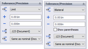
The standard does not define a "nominal dimensioning" method. What I assume you are advocating for is either limit dimensioning or unilateral dimensioning. While I would agree that these may be slightly more robust from a fitment or interchangeability standpoint as they may "suggest" to whoever is viewing/editing the drawing that there is a limit which should not be exceeded, it is not foolproof. Heres what they both look like in solidworks.

dimensioning_kccvqk.png


Theres nothing stopping me from putting a nonzero value on the minus side.

Additionally, while rarer there are cases where LMC is your functional target, as well as the size from which your VC is calculated. MMC is not the only solution.

Finally, your size tolerance is not the only thing which establishes your VC - it is the culmination of both your size tolerance and geometric tolerance. And while it may not impact the VC calculation, Datum Reference Frame and Datum Feature boundary condition(s) will have an impact on validation and your tolerance zones wrt your datum features. There are any number of ways which someone can unwittingly deviate from your design targets when modifying a drawing. At the end of the day its up to the designer and responsible engineer to be extremely careful about editing, reviewing, and checking drawings.

If this was the main thrust of your presentation, it seems like it could have been much shorter.
 
Paul Finch,

As per my terminology and using SolidWorks, I can model something at nominal size, use that feature to control the size of the mating feature, and I can apply ISO[ ]tolerances. The ISO[ ]tolerances are based on the fit that I want. This will be maintained even when I significantly change the size of the feature. I expect that the other intelligent CADs do this too.

When I am done designing, it is good practise to clarify dimensions for reading by the fabricator and inspectors. They need the numbers. They don't need the ISO[ ]codes.

If my feature is an accurate diameter for a machine shop, probably I will show limit dimensioning. This shows off the actual numbers the feature must conform to. I don't care about MMC. Everything in the range is good. If the fabricator can easily do my tolerances, they may be inclined to get as close to MMC as possible, but I don't care. Consider that I don't want to tell the fabricator what my part is for. An obvious failure mode is that the connection will be loose, and it will rattle. Alternately, the joint can bind due to thermal expansion, making MMC the failure mode. Note how the ANSI RC5 "medium[ ]running" fit allows clearances of 0.05mm to 0.12mm. The MMC condition can be as much of a failure as the LMC condition.

Look at my example, above. I can specify my forty millimetre diameter as [⌀]39.95/39.93 which is convenient for inspection, or I can go [⌀]40-0.05-0.07. That latter specification seems to bother some people, but it shows off the nominal model size in addition to the tolerances. If my fabricator works from the CAD[ ]model, this may be a safer specification. Don't assume your round part is going into a lathe. Joe[ ]Osborn might do it on a CNC mill.

Forget diameters. Let's control a complex outline with a profile tolerance. All the comments above still apply. The MMC condition affects fit and access. The LMC condition may affect structural rigidity and strength, or it may be providing enough "meat" to permit blind tapped holes on the side, or perhaps spot faces on the front. If I am specifying holes in castings that I will later machine out accurately, the LMC condition is my big failure mode.

--
JHG
 
I'm the one who said "keep it simple." However, when trying to explain an overall topic you have to cover all bases otherwise you get, but what about this, and what about that? Parts fit together on a MMC basis. LMC is only for controlling thin walls or whatever and has nothing to do with the boundary of interchangeability. When the standard says that the MMC boundary is "perfect" and is the true geometric form represented by the drawing, then there is beauty in its simplicity. This is the "go" condition of the Taylor Principle. The mid-range or LMC cannot be a basis for applying tolerances because they are imperfect and vary from part to part and frankly are a phantom in terms of Rule 1 definition.
 
Paul Finch,

The MMC condition determines that parts can be assembled. If I need an accurate sliding fit, LMC determines whether or not my parts rattle. Maybe I have a bunch of parts that assemble next to each other and whose edges must line up. When I apply tolerances to a drawing, I define an acceptable range of dimensions for which I will accept the fabricated part. I am solving multiple problems only one of which is interchangeability.

--
JHG
 
Paul,

As drawoh and I have both mentioned, design considerations are usually much more complex than just getting them to fit. Simplifying it to say thats the only consideration is disingenuous. Interchangeability is only one piece of the puzzle, as engineers and designers we have to consider all aspects.

When the standard says that the MMC boundary is "perfect" and is the true geometric form represented by the drawing, then there is beauty in its simplicity.

I'm not sure what higher meaning you're gleaning from rule #1. Your boundary of perfect form is at MMC if your feature is at MMC/RFS, it is at LMC if your feature (geometric tolerance) is specified LMC. It can be overridden by the Independency (I) symbol or any number of the other exceptions I noted previously - something as simple as a flatness or straightness tolerance. Thats it.

Also this envelope is not your only interface consideration. A hole of size 5.00+.01/-.00 with position .01@MMC to |A|B| must satisfy both a dia 5 boundary not constrained to any datum features (your rule #1 envelope) and a dia 4.99 boundary constrained to |A|B| (your VC). These boundaries are not necessarily, and not required to be, the same size.

The mid-range or LMC cannot be a basis for applying tolerances because they are imperfect and vary from part to part.

I'm again not really sure what you're trying to say here. Parts have variation, a drawing is exact no matter what we consider nominal or what dimensioning scheme we use.
 
Paul Finch said:
Keep it simple.

OK.

In simple terms, what it appears that you advocating is that without exception, MMC represents the condition in which a group of parts are most likely to have best interchangeability. This simply isn't true.

On top of that, it also appears (granted I have not absorbed your entire presentation; it's very dense, and it is a work day...) that you are advocating, basically, that all tolerances should be unilateral and MMC should never be exceeded. While this may make sense in certain scenarios, in the real world it makes manufacturing things more complicated than it needs to be.

Say I'm machining a surface (or trimming a part or milling a pocket. Whatever. Doesn't much matter) that needs to be 50mm tall, and I know that if this surface is ANY taller than 50mm, my parts will not fit. 50.000001mm is a failure.

I know to a certainty that if I make 1,000 of these parts and I've commanded my milling machine to give me 50mm height, I'm going to get some that are exactly 50mm but I'm also going to get some that are 50.01 and some that are 49.99 and so on.

If the drawing that's been handed to me by the engineer states in no uncertain terms that I can NEVER exceed 50mm, what am I to do? If I'm a smart machinist, I'm going to shift the target of my programming toward the center of the tolerance, however far away from the nominal (this is what that word means) target that may be, such that I produce the highest possible percentage of good parts. This in turn means that the center of my statistical distribution of finished dimensions is going to shift away from the nominal target, and toward the center of the tolerance. Depending on the machining operation, it may move a lot.

Point is this: when we set a value and add a tolerance, we are telling the machinist/fabricator/foundry/whomever two things: where we want the center of the statistical distribution of feature sizes to land, and how many of the inevitable outliers they get to count as good. If we, as designers, are smart and understand how are parts are going to be made (which we should) this may mean the tolerance value is not symmetric. But whether it is or is not, it is critical that we set what the target is. What you are doing, in effect, by setting MMC as the upper limit on a dimension and providing a unilateral tolerance is allowing whomever is next in the chain of custody to decide on their own what the true target value is for the manufacturing process. You've effectively just removed information from the game of telephone that we are already playing. There is no value added; you wind up with your drawings being less useful and carrying less meaning to the guy who has to interpret them.
 
when we set a value and add a tolerance, we are telling the machinist/fabricator/foundry/whomever two things: where we want the center of the statistical distribution of feature sizes to land, and how many of the inevitable outliers they get to count as good.

While this is a common assumption, this is actually not the case - and its been codified in Y14.5-2018 para 4.1 fundamental rules:

ASME Y14.5-2018 said:
(q) UOS by a drawing/model note or reference to a separate document, the as-designed dimension value does not establish a functional or manufacturing target

Its up to manufacturing/quality to determine their targets and from there based on process reliability determine their upper and lower process limits (at least for a shop which knows what they are doing) inside of the drawing spec limits to ensure 100% acceptance based on sample size and measurement uncertainty. Unless absolutely required by design, it would be generally inadvisable for this to be specified on the drawing.
 
You can quote ASME Y14 to the guy turning wheels on the Bridgeport or punching keys on the Mazak all you want - that guy does not care. What ASME Y14 says about nominal dimension values and what they mean in the real world are different things.

What that line actually does is give the guy turning wheels or punching keys the freedom to adjust his process away from the nominal value such that he provides the highest percentage of 'good' parts; it does not change the definition of what is or is not good, and it does not affect what the designer's original intent was. As designers, we are responsible for providing values that accomplish our design intent, independently of processing; ASME Y14 just gives the manufacturing guy an out when we make mistakes. Which, as humans, we do, whether we admit it or not.
 
I'm so glad we agree that whats in the standard should be largely ignored in favor of whatever the general consensus is, and should only be consulted when someone makes a mistake. I've seen that play out, it always ends well.

What that line actually does is give the guy turning wheels or punching keys the freedom to adjust his process away from the nominal value such that he provides the highest percentage of 'good' parts

Correct, this is exactly what I said. This would be beneficial to manufacturing and would allow them to adjust their process and targets without engineering imposing undue limitations - especially important when the engineering is done by a different party without intimate knowledge of the manufacturing process. This seems like a good thing, wouldn't you agree? You even said it yourself, design intent should be established independent of processing, establishing nominal values as manufacturing targets isn't exactly independent is it? This makes even less sense when you realize a nominal value, though less commonly, is not required to be within the tolerance zone - ie: .500 -.005/-.010

it does not change the definition of what is or is not good, and it does not affect what the designer's original intent was

I didn't say it did, on either point.

ASME Y14 just gives the manufacturing guy an out when we make mistakes

It does a lot more than that.
 
chez311 said:
I'm so glad we agree that whats in the standard should be largely ignored in favor of whatever the general consensus is,

Oh please. You know exactly what I'm saying.

Yes, it is true that in a perfect world, Y14 would would cover every possible scenario and prescribe exactly how to communicate design intent perfectly, and in turn manufacturing staff would interpret drawings exactly, according to what's prescribed in the standard, without error and without ambiguity.

We both know that those conditions are rarely true.

chez311 said:
This seems like a good thing, wouldn't you agree? You even said it yourself, design intent should be established independent of processing, establishing nominal values as manufacturing targets isn't exactly independent is it?

Of course it's a good thing; I never said it wasn't. As a designer, one of my goals should always be to make manufacturing's job of making good parts as simple as possible.

There's a very subtle difference between what I actually said and how you're interpreting it. If I put a hole dimension on a drawing at .500 with a tolerance, I am telling manufacturing what my ideal part looks like; my ideal part has a .500 hole. If they have to use a .495 drill bit to get the highest possible percentage of holes at exactly .500 (if we're operating on the assumption that my tolerance is symmetric and the process yields a normal distribution of sizes, than the most parts within tolerance and the most parts exactly at nominal are the same result), I do not care. I have communicated what I want, they have made a process adjustment to deliver it. It's not complicated. I am not dictating to them what drill bit size to use.

What OP is advocating is providing a window in which they can cut my hole; but by removing one of those three numbers, I am removing a critical piece of information. That's bad.

The point I'm really getting at is that, as you've stated (and I agree with you), the current standard design practice and what OP is advocating for eventually wind up in the same place; the difference is that the current design standard also is sensible in cases where the guy drawing the drawing and the guy reading the drawing are not experts on the interpretation of Y14; there is more room for error, and that is critical.
 
SwinnyGG,

I'm not suggesting that the standard can or should cover every possible scenario, or that we live in a perfect world. I am suggesting that it benefits everyone to have a better understanding of the standard to which a drawing conforms.

If I put a hole dimension on a drawing at .500 with a tolerance, I am telling manufacturing what my ideal part looks like; my ideal part has a .500 hole.

That pretty much how I interpreted it, and thats also similar to what OP is saying about MMC being the "ideal" part. Its just not the case. That may be what you assume to be the case, and it may also be the same assumption of whoever is reading your drawings - but its not what the standard says. And thats all it is, an assumption or generally held belief - but it is not universal, and above all is NOT unambiguous. Hoping that someone else has the same assumptions as the person who developed the drawing is not a good basis for robust design practice. If you want nominals to be manufacturing targets, you should state it as such clearly on a note or accompanying internal standard. The opposite could apply as well, if you have multiple unequal bilateral/unilateral tolerances (or nominals outside the tolerance zone) and do not wish or more likely do not care that they be used for manufacturing targets then you could also clearly state as much on a note - though except for possibly providing a cost advantage there is less incentive for this on the design side. In this case it greatly benefits the people making the part to know the standard well.

by removing one of those three numbers, I am removing a critical piece of information. That's bad.

I disagree. I don't think anyone would argue that limit tolerancing is a bad design practice by just providing your upper and lower limit on the drawing. In fact, it might even be better to remove any ambiguity or assumptions one might make about a nominal value.
 
chez311 said:
I am suggesting that it benefits everyone to have a better understanding of the standard to which a drawing conforms.

I agree that it benefits everyone if we all understand the standards at a high level; but unfortunately we live in the real world, where that isn't the case, and where 'go read Y14' is not an answer that's going to be taken well if someone askes you what something means (even if 'go read Y14' is what needs to actually happen).

chez311 said:
but its not what the standard says

Uh.... what? You're conflating a 'manufacturing target' with an actual definition of the part.

By the logic you're following, no dimensions of any kind mean anything, because they all represent a 'manufacturing target' which is disallowed by the standard.

The entire point of Y14 is to clearly define how designers communicate to manufacturing two things:

1) what perfection looks like
2) what deviations from perfection are allowed

If you look at a drawing and don't consider that the drawing shows the ideal final result, than none of the applied tolerances mean anything.
 
If you look at a drawing and don't consider that the drawing shows the ideal final result, than none of the applied tolerances mean anything.

If this is the case, then if you look at a drawing and don't consider that someone may not interpret it the way you think they should, and you blow off the standard that governs how a drawing should, and shouldn't be interpreted, then the standard means nothing and we're back to doing things the way my great-grandfather did them.

...where 'go read Y14' is not an answer that's going to be taken well if someone askes you what something means...

If someone asks me what something means, "go read Y14.5" is definitely not a suitable answer. I don't think chez ever said that though. The answer to this is actually in Y14.5 but some have chosen to ignore it. It's a fundamental rule, in fact. This argument is already settled, it's just a matter of accepting that the answer isn't what one thought it would be, or even should be.

You can quote ASME Y14 to the guy turning wheels on the Bridgeport or punching keys on the Mazak all you want - that guy does not care.

He should. If he makes a living reading prints then he should know, or at least care about, how to interpret those prints correctly. That's kind of like saying that truck drivers don't care about the rules of the road, they just want to transport stuff.

John Acosta, GDTP Senior Level
Manufacturing Engineering Tech
 
powerhound said:
It's a fundamental rule, in fact.

Which was added in 2018.

Do you think there has been a dramatic change in how drawings were created and interpreted within the last three years?

 
I agree with John wholeheartedly.

By the logic you're following, no dimensions of any kind mean anything, because they all represent a 'manufacturing target' which is disallowed by the standard.

Thats very clearly not what I said. Not even remotely.
 
You two are completely misunderstanding what I'm saying- I'm not blaming you for that, clearly I haven't clarified exactly enough.

I am not blowing off the entire Y14 standard. I have lived by it, advocated for it, and argued against people in my supply chain who have a 'GD&T is a waste of time attitude' for more than a decade.

The disagreement here is that you seem to be interpreting one minor change, added in the 2018 edition and not previously codified, as a fundamental and standard-altering change in approach; my interpretation is that that added subphrase serves only to aid in the ability of a Y14 compliant manufacturer to alter their processes as necessary without blowback from an engineer or designer. I do not believe it was intended to create a fundamental shift in the way drawings are created or interpreted. The interpretation you are advocating is exactly that.
 
Status
Not open for further replies.

Part and Inventory Search

Sponsor