Continue to Site

Eng-Tips is the largest engineering community on the Internet

Intelligent Work Forums for Engineering Professionals

  • Congratulations cowski on being selected by the Eng-Tips community for having the most helpful posts in the forums last week. Way to Go!

Degrees of freedom for an orientation control 3

Status
Not open for further replies.

Belanger

Automotive
Oct 5, 2009
2,450
For the given parallelism tolerance, would you say that datum A constrains 2 D.O.F. or that it constrains 3 D.O.F.?
I can elaborate if you're curious why I pose this question.


parallel_olzwbt.png


John-Paul Belanger
Certified Sr. GD&T Professional
Geometric Learning Systems
 
Replies continue below

Recommended for you

That answer requires nuance between what we define as the DOF the datum feature itself constrains and in what DOF the tolerance zone is constrained. If we're going by ASME then 6.4 I think supports this. Ie: in your case your datum feature A constrains translation/rotation (u,v,z) but your tolerance zone is only constrained in rotation (u,v).

ASME Y14.5-2009 para 6.4 said:
Orientation tolerances are constrained only in rotational degrees of freedom relative to the referenced datums; they are not constrained in the translational degrees of freedom. Thus, with orientation tolerances, even in those instances where datum features may constrain all degrees of freedom, the tolerance zone only orients to that datum reference frame.

I am curious why you posed the question, while I think distinction/nuance in these matters are important - it is interesting to note how the distinction matters in an actual application.
 
I might as well tip my hand... I maintain that this constrains 3 DOF due to the nature of datum A itself, and I appeal to Fig. 7-3 of the 2018 standard as my basis. But others have said that it constrains only 2 DOF because this is an orientation control (not location), so translation along the Z axis is irrelevant.
I agree that translation is irrelevant to the measurement of parallelism, but I'm going with the ASME view on this.

My question was sort of a poll to see if any of you have heard this other viewpoint that a primary datum plane only constrains 2 DOF.

John-Paul Belanger
Certified Sr. GD&T Professional
Geometric Learning Systems
 
This came about in a discussion with an associate here. It wasn't in regards to the application or interpretation (which is super easy for this drawing). It was a theoretical and semantics discussion.
Yes, chez, you hit on the nuance of the question. Since our discussion was on the datum, so I say that datum A indeed constrains 3 DOF.

But your reply gives me the wording I was looking for to explain this to my associate:  The part is constrained in 3 DOF, but the tolerance zone is constrained in 2 DOF.
 
I would simply say that datum A constrains 3 DOF, only two of which are relevant for the orientation control under question. Other controls may reference the same datum feature so the third DOF constraint is not canceled in any way.
 
All,

Let me extend a little bit your discussion (and avoid, I hope, its natural death)…

Is this the reason on why ISO introduced <> symbol?

ISO 5459-2016 states that <> modifier is used for orientation constraint of datum without constraint of the tolerance zone, intersection plane, orientation plane, direction feature or collection plane.
The complementary indication is <> if the datum is not used to lock the orientation and location degrees of freedom of tolerance zone, but only to orientate the tertiary and/or the secondary datum.

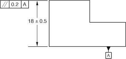
How the same figure in ISO would look like?
(Few months ago was another discussion on a different site, but still not clear to me hence I am opening one here too)

We can introduce the right feature (or the left one) of the shown part, as an additional datum feature, for the sake of discussion.

 
Belanger,

If that part is thick, datum[&nbsp;]A constrains one degree of translation, and two degrees of rotation. I would not apply that as a primary datum unless the part were thick.

If that were a piece of sheet metal, then one of the faces should be the primary datum, and the datum feature shown would control two degrees of freedom.

In the context of your parallelism specification, then yes, only two degrees of freedom are relevant. My mind does not work this way. Translation remains irrelevant until I apply a profile or positional tolerance somewhere. Figure[&nbsp;]7.3 (Figure[&nbsp;]4.3 in ASME Y14.5-2009) is showing the meaning of the datum specification outside the context of a feature control frame.

Can a primary datum control only two degrees of freedom?

--
JHG
 
J-P,

Short answer - I would say that datum A constrains 3 degrees of freedom.

The Y14.5-2009 excerpt that chez311 referenced, particularly the bolded statement, makes this very clear. To me, anyway. Despite this, not everyone sees it the same way. I have talked to people at ASME meetings, including current members of Y14.5, who would say that Datum A constrains 2 degrees of freedom despite the statements in section 6.4. These clarifying statements only appeared in 2009 - in 1994 and previous, they were not present.

I remember discussions about whether or not customized DRF's duplicated the effect of composite FCF's. There was an argument that they did, and that composite FCF's could therefore be phased out. This argument was based on the idea that the datum features referenced in the FRTZF (lower segment of a composite FCF) only controlled rotational DOF's. The text in Y14.5 unfortunately left room for this interpretation, if one is willing to cherry pick certain statements such as this one that was still present in 2009:

"If datums are specified in a lower segment, they govern the rotation of the FRTZF"

The situation is complicated further by the fact that ISO does it differently, as greenimi pointed out.


Evan Janeshewski

Axymetrix Quality Engineering Inc.
 
Has been brought to my attention that ISO 5459-2016 is Zurueckgezongen meaning that the above mentioned ISO standard never seen the light of the day. (2016 version has been draft and never released before got canceled/ withdrawn).

What that does mean for this discussion: <> symbol is no longer valid. (don't confuse it with >< which is still valid and "substitute"/ aid for ASME's composite callouts concepts). I think the intent was to use / introduce <> symbol but after further debate ISO decided not to. I guess ISO has its own sets of problems/ issues and the published ISO draft standards (that some people have access to) do not help much.

Sorry for any confusion that might cause.

Might be a minor correction since this discussion in an ASME based one.


Status
Not open for further replies.

Part and Inventory Search

Sponsor