Continue to Site

Eng-Tips is the largest engineering community on the Internet

Intelligent Work Forums for Engineering Professionals

  • Congratulations waross on being selected by the Eng-Tips community for having the most helpful posts in the forums last week. Way to Go!

Datum referring to itself: Datum assigned to FCF which contains same datum as secondary

Status
Not open for further replies.

Mahesh AC

Automotive
Jul 14, 2017
3
Datum-to-itself_d6t8bc.png


Recently came across a drawing spec, where a datum was defined onto a feature control frame, and the feature control frame had the same datum as secondary.
In the picture, Datum 'B' is defined to a profile of surface FCF, which uses Datum 'B' itself as secondary. (It is a flat surface that FCF is attached to)

Had to pause for sometime and it felt like 'Interstellar movie'.
Is it allowed in ISO GPS, to define this way, or is it a mistake due to not being careful about the redundancy?
 
Replies continue below

Recommended for you

I'm interested to hear what is the case in ISO (I have a suspicion pmarc knows) however in ASME its a supported practice. Its especially common in molded/cast parts with all-over profile tolerance notes. It was previously a generally understood practice however its been codifed in the most recent 2018 version. It depends on the exact application (datum targets vs features) however the typical application shown below means half the tolerance zone is usable for non-FOS planar datum features. This can change depending on if FOS datum features are used, etc..

Theres some debate about the proper terminology, but I typically refer to these not as redundant but "self-referencing". In regular practice I try to avoid this if at all possible, but as I said its not uncommon in certain industries.

A below example from ASME Y14.5-2018, I do not have a similar example from ISO if it exists. Perhaps someone can provide it. (note - ignore the way the shaded portions are drawn. Thats a well documented mistake in the document format)
fig_11-21_drrppe.jpg
 
It is hard to answer the question without knowing more details about the drawing, e.g. what all datum features are and how they are toleranced. Is datum B derived from datum targets or maybe from the entire flat surface? Lack of B1,2,..n notation next to the datum feature symbol B seems to suggest it is the entire surface. Is it really a single surface? CZ used in the tolerance frame causes some doubts in my head.

Also, I don't think there is anything in ISO GPS standards specifically not allowing to use the same approach as shown by chez311.
 
Thank you Chez311 and pmarc.

To add some more clarity, yes, it's for a plastic molded part.

Datum A is a collection of surfaces - all around of a shroud's internal wall.
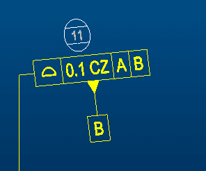
Datum B is a single planar surface perpendicular to the wall, and No targets used (which makes it more ambiguous as the area of interest is same for the measurement and the datum). And of course CZ added to a planar surface is an overdo in this case as it is a single surface.

@Chez311; As you said, In your example is a definition that is becoming commonly used for molded parts as it can put a control on all the rest of the areas on part other than functionally important with a single annotation, and Functional requirements could be later defined as needed.
But this is mostly used with 3 Datum / 6 degrees locked.
Now the doubt from the query: Is there a change in the meaning when only Datum A in the FCF is used in that case, because with B in FCF or without it, the surface is meant to be a chebichev Best fit (correct me If I'm wrong)since no additional degree constraints other than A (&B) is mentioned/needed.
 
 https://files.engineering.com/getfile.aspx?folder=a462d018-8183-4ba1-9776-5549f5fdee21&file=Annotation_2020-09-01_132619.png
Mahesh AC said:
And of course CZ added to a planar surface is an overdo in this case as it is a single surface.

In that case what makes you think that presence of B in the profile callout for datum feature B is not an overdo too?

Additionally, I am not sure I agree with the order in which the datum features have been referenced on this drawing. Based on my experience with this type of components, the design intent is usually to specify planar mating face as primary, not the other way around. But maybe this is an exception.
 
Status
Not open for further replies.

Part and Inventory Search

Sponsor