This is a fairly basic question but I've struggled to find a reference discussing it.
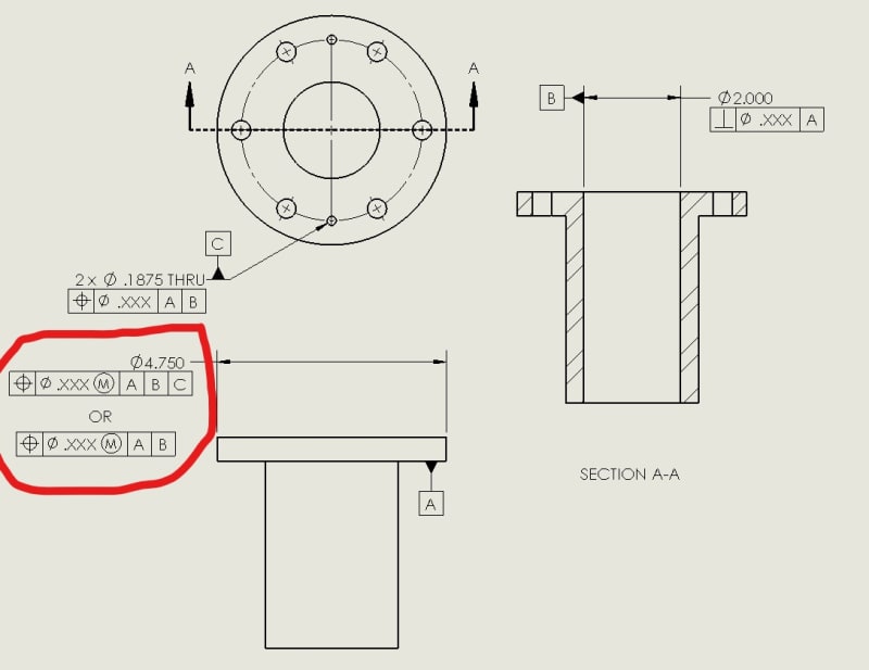
So I've got a stepped cylindrical part that looks like a big tophat bushing. The primary datum is the "flange" face of the tophat that seats against a plate. The secondary datum is the hole through the center of the bushing that will have a shaft go through it. The tertiary datum is two holes that will have dowels press fit into them. Those dowels will go into mating holes on the other part, constraining clocking. After all that, there is a 6-hole bolt pattern that clamps it in place.
So my question is, for the axisymmetric features of this part, such as the flange outer diameter, it makes sense to me to control their location using a position tolerance because I'm not particularly worried about their surface forms. When I create these position controls, it feels like I only need to reference datums A and B to fully define their locations because they are axisymmetric and do not have a "clocking." However, the bolt hole pattern will be defined with position tolerances referencing the A,B,C datum reference frame which is the fully constrained assembly reference frame.
As circled in my drawing below, is there any actual difference between the two position control options I gave for the outer diameter? Does adding datum C somehow change the tolerance zone even though the feature is axisymmetric?
Thanks!


