Continue to Site

Eng-Tips is the largest engineering community on the Internet

Intelligent Work Forums for Engineering Professionals

  • Congratulations waross on being selected by the Eng-Tips community for having the most helpful posts in the forums last week. Way to Go!

Datum Reference Frame for Position Control on Axisymmetric Part

Status
Not open for further replies.

Gwad94

Mechanical
Nov 21, 2019
3
This is a fairly basic question but I've struggled to find a reference discussing it.

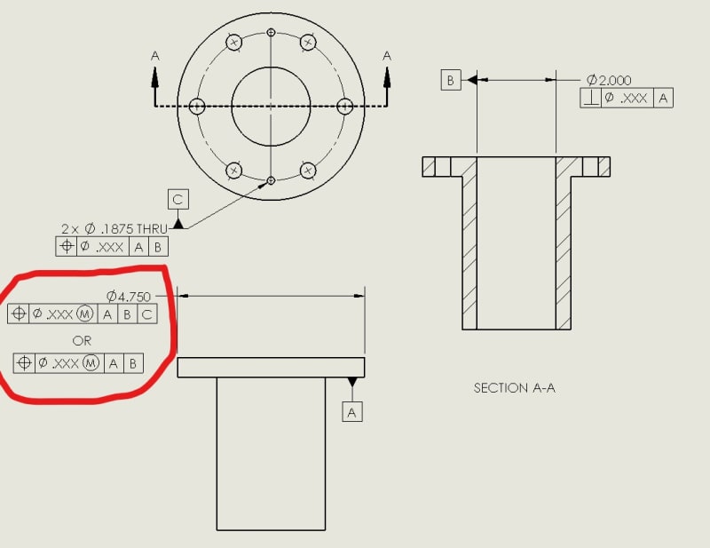
So I've got a stepped cylindrical part that looks like a big tophat bushing. The primary datum is the "flange" face of the tophat that seats against a plate. The secondary datum is the hole through the center of the bushing that will have a shaft go through it. The tertiary datum is two holes that will have dowels press fit into them. Those dowels will go into mating holes on the other part, constraining clocking. After all that, there is a 6-hole bolt pattern that clamps it in place.

So my question is, for the axisymmetric features of this part, such as the flange outer diameter, it makes sense to me to control their location using a position tolerance because I'm not particularly worried about their surface forms. When I create these position controls, it feels like I only need to reference datums A and B to fully define their locations because they are axisymmetric and do not have a "clocking." However, the bolt hole pattern will be defined with position tolerances referencing the A,B,C datum reference frame which is the fully constrained assembly reference frame.

As circled in my drawing below, is there any actual difference between the two position control options I gave for the outer diameter? Does adding datum C somehow change the tolerance zone even though the feature is axisymmetric?

Thanks!

Axisymmetric_Position_Controls_nvmwb2.jpg
 
Replies continue below

Recommended for you

If you leave out C, the distances between the holes of the considered pattern and the 2 dowel pin holes are uncontrolled. You could have wall thickness of a micron between them and the part would be considered good.
 
Burunduk,

Notice that OP only asked about datum references on the outer circular profile, not the pattern of holes.

Gwad94,

Since you have them referenced at RMB I would say there is no difference. If B and C were referenced at MMB there could be slightly different result during gauging/measurement depending on the relative size that the pattern of holes and central hole come in at. Imagine if the two dowel holes come in at MMC and the central hole at LMC, the two dowel holes would end up constraining all remaining translational and rotational DOF.

It's important to note that precedence and material boundary of referenced datum features does not change the tolerance zone, only the datum feature and simulator relationship, and simulator behavior. This distinction may be a bit nuanced as the way datum features are referenced on two different tolerance zones/FCF's may affect the relationship between the two tolerance zones ie if C is omitted from a position tolerance on the pattern of 6 holes, but this is due to the datum feature and simulator relationship.
 
It's likely that [A|B] is a bad choice, but the parts likely won't use the perpendicularity tolerance where you have specified it, so it's an academic exercise without consequence.
 
chez311, thank you for the correction.
From some reason I thought the question was about the pattern of 6 holes.

I would say that from the description of function I tend to suggest [A][B(M)] as the datum reference frame for the flange OD position control. Adding an MMC modifier after the tolerance value can also be considered.
 
Great reply, chez311. Thank you. Sounds like we are in agreement that with the datum references at RMB there is effectively no difference in the position control of the outer diameter for A|B vs A|B|C for this situation. Something about there being no difference really threw me off so I wanted to check with everyone here. It does make sense to me that if the datums are referenced at MMC that the datum simulator's behavior with the part would allow for some different results.

Thinking about your comment on the datum simulator situation where the dowel holes constrain all the remaining degrees of freedom has made me realize that the datum reference frame I'm using doesn't really make sense. The dowel holes are the authority for setting the translation as well as rotation of the part, so I believe the two dowels should be datum B, and the reference frame A|B is a fully constrained datum simulator. Since the holes on this part are press-fit and they mate with clearance holes on the other part, I don't think that they should be referenced at MMC. The inner bore has a pretty loose clearance fit with a shaft, so it doesn't actually constrain the part. Instead that inner bore needs to have its position controlled relative to the location that the two dowels set the part at.

 
Gwad94,

Glad to be of help - I would say your intuition is correct. If there are dowel pins press fit into the 2X .1875 holes the position tolerance for those two holes should be RFS and these are the features which constrain [x,y] translation and [w] rotation (with the convention that z is normal to datum feature A) in the assembly then they should be datum feature B and |A|B| at RMB should be referenced.
 
Consider designating one of the dowel pin holes as datum feature B and the other one C and reference [A][B-C] for controls of other features.
 
Burunduk,

Presumably you would leave the dowel holes controlled with a 2X position tolerance to A?
 
Gwad94,

Is there any chance that you could define the part with the dowels installed into the holes and then (the dowels) used as datum pattern B?
 
Burunduk, does treating each dowel hole separately change my datum simulator if they are still both controlled with the 2X position tolerance to A? Or is it just a preference on notation? I kind of like showing the pattern as a single datum so it's clear they hold equal sway in determining the part's location.

pmarc, that's an interesting idea and should be possible. I'm not sure what benefit that provides other than being the most representative of the assembly. It would also let me require some perpendicularity tolerance on the installed pins that encompasses the projected tolerance zone into the mating part. The pins are ground so they won't really give me any datum shift at MMC.
 
Gwad94 said:
does treating each dowel hole separately change my datum simulator if they are still both controlled with the 2X position tolerance to A?

I know this wasn't directed to me, but this is precisely why I asked the question to Burunduk - if both are held to A and referenced as a multiple datum feature B-C it does not change your simulator/behavior and I see no reason to adopt this notation over treating the 2X pattern as B. It would only make a difference if one of the dowel holes C was controlled by a tolerance Zone held to A|B instead of just A. I wouldn't recommend this though unless the mating part had one circular and one slotted hole (or one round/one diamond pin - etc..). Even then if the part could be assembled either way with the slotted hole on either dowel I wouldn't recommend it.
 
The dowel holes are the authority for setting the translation as well as rotation of the part, so I believe the two dowels should be datum B, and the reference frame A|B is a fully constrained datum simulator. Since the holes on this part are press-fit and they mate with clearance holes on the other part, I don't think that they should be referenced at MMC. The inner bore has a pretty loose clearance fit with a shaft, so it doesn't actually constrain the part. Instead that inner bore needs to have its position controlled relative to the location that the two dowels set the part at.

Based on this description, and assuming that the tolerances are mainly intended to ensure that clearance is possible, I think the flat surface is the only datum feature reference you need.

If you tolerance the assembly of the part with the two pins pressed in, something like the following would probably be appropriate:

2X ⌀.1877±.0001
[box]⌖[/box][box]⌀.005Ⓜ[/box][box]A[/box]

6X ⌀.400 THRU
[box]⌖[/box][box]⌀0Ⓜ[/box][box]A[/box]

⌀2.000 THRU
[box]⌖[/box][box]⌀0Ⓜ[/box][box]A[/box]


If you prefer to tolerance the part without the pins, something like the following would achieve a similar result:

2X ⌀.1875 THRU
[box]⌖[/box][box]⌀.005Ⓟ.250[/box][box]A[/box]

6X ⌀.400 THRU
[box]⌖[/box][box]⌀0Ⓜ[/box][box]A[/box]

⌀2.000 THRU
[box]⌖[/box][box]⌀0Ⓜ[/box][box]A[/box]


Applying the three position tolerances as a simultaneous requirement like this matches the assumed functionality a bit better than using the pin holes as a secondary datum feature reference (RMB) for the other tolerances. The real assembly does not mate with your part using simultaneously expanding pins fixed at the basic separation.


pylfrm
 
Gwad94 said:
Burunduk, does treating each dowel hole separately change my datum simulator if they are still both controlled with the 2X position tolerance to A? Or is it just a preference on notation?

I assume you use the ASME Y14.5 standard. If it's the 2009 edition (the one I am most familiar with), it doesn't show examples or provides explicit instructions on how a datum feature simulator should behave for a pattern of features of size referenced RMB, the way you specify it. Where similar patterns are used as a datum feature reference such as in fig. 4-35, the datum feature symbol is shown attached to inscribed/circumscribed theoretical cylinders or plane distances tangent to the cylindrical features, which imposes a different type of datum feature simulator than intended in your case. Where the datum feature symbol is associated with the size and number of the features, they are referenced MMB (fig. 4-26).

chez311 said:
Burunduk,

Presumably you would leave the dowel holes controlled with a 2X position tolerance to A?
yes, I would.

pylfrm said:
The real assembly does not mate with your part using simultaneously expanding pins fixed at the basic separation.

I agree. And this is indeed the most probable implied datum feature simulator behavior when the datum feature symbol is associated with the size and number of features specification for the pattern and referenced RMB, although this doesn't seem to be covered by the standard and some things remain unclear. For example: in reality both expanding pins will not be constrained by the considered holes simultaneously. Since the pins are "simultaneously expanding", should one pin stop expanding as soon as the other does (and thus may leave some clearance with its mating hole)?

(pylfrm - we discussed it recently).
 
Somehow related with what it's been discussed in this thread, was also, at least tangentially, debated here:
"Validity" discussion

I like the idea of a single datum feature shown in the DRF, but in order to do that the level of education of the readers of such drawings should increase (just a bit).

What I can learn for this discussion and also from the one I just referenced above is the fact the more datum features are shown in the DRF the more stringent the design become.
Simultaneous requirement (and only one -single- datum shown) is the best for accepting all --functional- parts.
 
it doesn't show examples or provides explicit instructions on how a datum feature simulator should behave for a pattern of features of size referenced RMB, the way you specify it.

I'm not clear on how you believe |A|B-C| (each pin separately B and C) suggests a different behavior over |A|B| (both pins together B). Actually Y14.5 does provide instructions, the fact that the example includes two coaxial FOS with zero basic location does not mean the behavior of the simulators is any different for nonzero basic location.

Y14.5-2009 said:
4.12.4 Pattern of Features of Size at RMB
Where RMB is applied in a feature control frame to multiple datum features of size used to establish a single datum, the datum feature simulator of each feature shall be fixed in a location relative to one another. The datum feature simulators shall expand or contract simultaneously from their MMB to their LMB until the datum feature simulators make maximum possible contact with the extremities of the datum feature(s). See Fig. 4-25.

Since the pins are "simultaneously expanding", should one pin stop expanding as soon as the other does (and thus may leave some clearance with its mating hole)?

I'd be interested to hear pylfrm's thoughts on this. My interpretation is that both pins start at the holes MMB and expand towards LMB simultaneously but there is no suggestion they must stop simulatenously. Even if one expands to its maximum extent first (ie: cannot expand any further) the second pin continues to expand to its maximum extent. See the above referenced 4.12.4 - it does not say "until ONE of the datum feature simulators" or "until the FIRST datum feature simulator" it says "until the datum feature simulators" - note the plural form, I don't see why one would interpret this any other way besides referring to all simulators in the pattern.
 
Gwad94 said:
pmarc, that's an interesting idea and should be possible. I'm not sure what benefit that provides other than being the most representative of the assembly. It would also let me require some perpendicularity tolerance on the installed pins that encompasses the projected tolerance zone into the mating part. The pins are ground so they won't really give me any datum shift at MMC.

The benefit is that this would control the true features responsible for orienting and locating the part in assembly (it would let to avoid application of projected tolerance zone concept) and foremost it would help to visualize / realize that because the mating features are clearance holes, referencing the datum pattern at RMB isn't really good choice (as stated by pylfrm, the mating holes aren't simultaneously expanding features at the basic separation).
 
For what it's worth, this is what ISO (ISO 5459:2011) says about establishment of a single datum axis from multiple datum features referenced RMB (using ASME terminology):

bbbbbb_frvpua.jpg
 
Gwad94,

I forgot to complain about your failure to specify which drawing interpretation standard you're using. It's best to include that information when you start the thread, but better late than never. I assumed ASME Y14.5-2009, and will continue to do so unless I hear otherwise.

Also, I forgot to note that the tolerances applied to the pins in the first scheme I presented should only be applied to the exposed portion of their surfaces.


My interpretation is that both pins start at the holes MMB and expand towards LMB simultaneously but there is no suggestion they must stop simulatenously. Even if one expands to its maximum extent first (ie: cannot expand any further) the second pin continues to expand to its maximum extent.

If one pin cannot expand any further, I wouldn't call continued expansion of another pin "simultaneous".

As I've mentioned in other threads, I think the bottom line is that the meaning isn't fully defined. This ambiguity is probably tolerable in many cases, but avoiding it is another reason I often prefer to use the simultaneous requirement approach.

I see no reason to believe that the number of datum feature identification letters used for the pattern would affect the meaning of the tolerance.


pmarc,

Is it the single largest distance between either filtered feature and corresponding associated feature which is to be minimized? The fact that "maximum distances" is plural in the description for items 7 and 8 makes me unsure of the intended meaning. Unfortunately I don't have ISO 5459:2011.


pylfrm
 
chez311 said:
Actually Y14.5 does provide instructions, the fact that the example includes two coaxial FOS with zero basic location does not mean the behavior of the simulators is any different for nonzero basic location.

Fig. 4-25 which is referred to in para. 4.12.4 shows an |A-B| DRF so it's more like the |A|B-C|, which perhaps can be different than something akin to fig. 4-26 only with the pattern of features referenced RMB instead of MMB - this is not shown in the standard. Regardless, I accept that the paragraph itself can be understood as applying to both cases. I would prefer to specify it in a way that can be interpreted by the standard more easily (represented in a figure). However, if the pattern of RMB datum features of size consists of more than 2 features this may be problematic. Not so in the case of the OP.

pylfrm's suggested scheme, based on simultaneous requirement seems to be the most elegant and appropriate solution, given that the drawing users are proficient enough, as greenimi noted.
 
Status
Not open for further replies.

Part and Inventory Search

Sponsor