Continue to Site

Eng-Tips is the largest engineering community on the Internet

Intelligent Work Forums for Engineering Professionals

  • Congratulations waross on being selected by the Eng-Tips community for having the most helpful posts in the forums last week. Way to Go!

Cutting Bottom Flange of an existing beam

Status
Not open for further replies.

HarpreetJagdey

Structural
Apr 17, 2020
8
Hello all
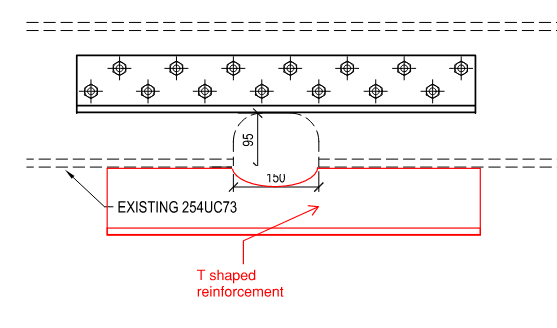
I am working on this steel skid where I have to make access for the drainage pipes.
The bottom flange of UC254 has to be notched for a length of 150mm and depth of 95mm.
The beam span is 7.2m with intermediate transverse beams and the notch is in the centre of beam where moment is the maximum.
To withstand the design moment, the section has to be strengthened. I am looking to add two equal angles at the web for a length of 700mm, bolted to the web of existing beam via M16 bolts at 50mm staggered spacing. I need to design the bolts so as to make it act an integral section.
How do I calculate the bolt force required (longitudinal/composite action shear force)

Refer to attachment please.
 
 https://files.engineering.com/getfile.aspx?folder=8d7ece25-803e-4647-a49d-4c0965aad468&file=SKETCH_ANGLES.pdf
Replies continue below

Recommended for you

What is stopping you from going underneath of the UC with the piping?

If this skid is fully supported by a slab, then I don't see an issue. If it is suspended, I don't see why they need to cut the flange.
 
Hi jayrod
Thank you replying buddy.
The drain pipe be following the design slope and will be passing through the webs of adjacent beams. On this particular one, the drain is clashing the bottom flange.
There are other services running in the area which prevents the drain pipe to be dropped lower. It is quite tight as far as access is concerned.
 
Well it looks dreadful to me and if it looks bad then it is almost certainly bad.

Can't you weld it?

Bolting won't give you the strength you need once you've hacked away at the bottom flange.
Additional plates under the flange would be better if you really can't shift it.

There is always a better way.

Bigger UC for this one?
Re routing the drain?
Having a short horizontal section. So yes, no continuous fall but needs must. Or reduce the fall for a short section to avoid cutting the flange. You really don't want to do that.

A 7m wide span is not to be sniffed at here.

Remember - More details = better answers
Also: If you get a response it's polite to respond to it.
 
Thank you for replying Littleinch

Why do you think bolting wont give me that strength? Would it not add the strength due to composite action if the bolts are designed to take the full capacity shear flow?
Would it not act as a smaller depth I-beam considering the fact the angle is nearly 300mm into the full depth of section on each side of notch?
 
I like this idea much better, and welded.
image_cgbxul.png
 
The bolted connection is better than nothing, but it won't replace the flange you've removed.

Bolts have to fit through holes which are bigger than the bolts. Thus to get your shear flow in the bolt, the original beam needs to deflect in order to engage that bolt, Thus it is already under stress / flex before the reinforcement starts to work.

Also it then introduces high intensity stresses in the web which isn't really designed for that.

Hence welding, which requires no deflection before providing re-inforcement is mush better.

I don't know who is reviewing or signing this off, but I think the client will take one look at it and tell you to do better. I know I would.

Remember - More details = better answers
Also: If you get a response it's polite to respond to it.
 
Thank you guys for the input. Will take your recommendations on board.
 
Do the way jayrod indicated. Your method might work strength-wise, but you have a beam with varies member stiffness that would cause large deflection at the notch. And like LittleInch pointed out, you might not be able to replace the lost section without other complications.
 
The problem we have is that no hot work is permitted and solution has to be bolted. This is a live gas plant.

What I can do is look into is to design a spliced connection with cover plates on the web and top and bottom flange. Can add shims at the bottom flange cover plate in order to avoid the pipe intrusion beyond the bottom flange of the beam.

What are your view on it.

 
 https://files.engineering.com/getfile.aspx?folder=4f21d2f7-d9bc-49d4-b25a-69c57e7cc9b7&file=SKETCH_splice1.pdf
The flange cover plate is a much better solution than the initially proposed angle as it maintains a much more similar moment of inertia. Depending on shear demand you may find that you don't even need to to reinforce the web.

 
I may try this to smooth out stress flow in the original web a distance away from the cut. I think a finite element analysis can provide better insight to find the optimum solution.
 
Far far better than plan A.

Remember - More details = better answers
Also: If you get a response it's polite to respond to it.
 
Not exactly the same situation, but I had a project where I had to shore up the steel frame while the bottom flange was removed and replaced to give more headroom. I did not design the modified beam. Here is the detail for the modification. It worked fine as far as I know. The W30 was turned into a W21.


www.PeirceEngineering.com
 
 https://files.engineering.com/getfile.aspx?folder=84c12b18-a656-48da-b12b-e9566c6630c4&file=Partial_Plan_-_Flange_Removal.pdf
Thanks again for input guys.

PEinc - if I had the option to weld the strengthening measures, the life be much easier then. The strengthening has to be a bolted one and in have few space restraints. I am hoping to get survey information from site sometime next week and will take it from there then.

I managed to check them beam in FEA. As expected, the notch will be highly stresses on its own. Adding a the cover plates at top and bottom brings it into safe zone. Attached file for information. based on S355 steel.

I have enough info now to justify the strengthening measures.

Thank you so much for all the input from all the members. Its always healthy to discuss when in doubt.

 
 https://files.engineering.com/getfile.aspx?folder=04a6a0dd-cf0e-4618-a8b6-ea2035516ed1&file=Slide1.JPG
Make sure you have considered the worst loading case. Beam internal stresses seem low. I forgot to attach my sketch on last response, which was to suggest extend the plates all the way down to the bottom flange to further smooth out the stress around the cut.
 
retired13, if you look at the original beam stress with notch, the stresses are very low as well apart from the notched section.

Just need to make sure plates are extended far enough to smoothen out the stress
 
I saw both, both were low, so that's why to remind you to double check the load case. Also, don't forget to check deflection at the cut.
 
Status
Not open for further replies.

Part and Inventory Search

Sponsor