Ab1869
Aerospace
Hello,
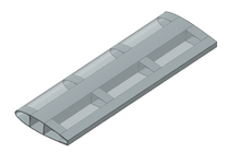
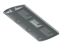
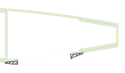
Let's say I have this composite wing structure: center box spar, aft spar, ribs and a upper/lower wing skin all bonded together. I want to make a rectangular cutout on the lower wing skin and either show this is good or size an externally bonded "donut" doubler around the cutout, all via hand calcs.
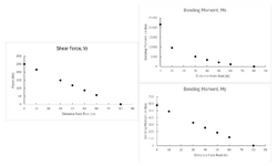
I used Example A5.12 in Bruhn to generate the attached shear force and bending moment diagrams about different stations of the wing (Mx is about the chord and My is about the spanwise axis of the wing). These are resolved about an axis 40% of the chord. From here, I'm not sure how to proceed.
I'd assume the skin in this area would be experiencing some combined loading: in-plane tension due to bending, as well as some shear due to torsion.
Would I go to A15 in Bruhn (shear flow in closed-thin walled section) and analyze the stresses prior to the cutout in this cell? But once I introduce the cutout, it's no longer a closed-section right? How would I compare the pristine to the cutout cell? Or is this a plates/shells problem?
This is all theoretical and none of this is going to fly. I'm just working on this out of personal curiosity and possibly a project to show on a portfolio. I went to school for mechanical engineering so roleplaying as an aero engineer here. I appreciate any guidance you could provide!


