Thank you for the clarification.
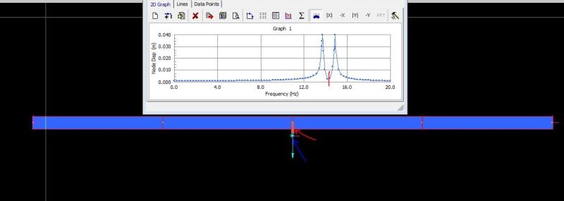
Here is a small example of a tuned mass damper (TMD). Pinned beam with first bending resonance at about 14 Hz.
The tuned damper is tuned to that frequency, thus in the frequency response when driven with a central load (arrow below), we should expect a split in that frequency due to the tmd, and a drop at the so called anti-resonance of the system (that is the freq. where the tmd is driven, and beam is almost still, just a 2 dof mass spring system).
All this can be seen in the image below. It is done in Strand7 but it is a one general approach and that can be used (other ways also to do this) - the point transnational mass of the tmd, is represented on a remote node (blue arrow marking below) that is connected via a spring-damper element (red arrow marking below) on to the central node of the beam elements. 2 DOF have been suppressed (out of plane and along beam axis at the point mass node), just to make this easier and since there is no spring stiffness horizontally, only along the spring element dir. thus axial stiffness.
This is just an example for reference but illustrates how it can be modelled, and how some FEA users might have modelled it in the past (of course damping can be adjusted so to change the response further - in this one little damping is used as seen since the peaks are quite sharp - again this is just to show how this can be modelled - since the spring element are not depended on their length it does not matter since stiffness K will be what one inputs, thus it is not element length dependent and not like EA/L like for a proper truss element where the element length is important, and comes in to the element stiffness - of course the distance might have an influence on the mass matrix (especially if it is a consistent matrix), but if the tmd mass is small compared to the structure mass, then that should be small).