Continue to Site

Eng-Tips is the largest engineering community on the Internet

Intelligent Work Forums for Engineering Professionals

  • Congratulations IRstuff on being selected by the Eng-Tips community for having the most helpful posts in the forums last week. Way to Go!

Corrosion repair of CHS 5

Status
Not open for further replies.

NewGuy132

Structural
Oct 15, 2021
4
I'm new to brownfields mining projects and one of my first tasks is dealing with some heavily corroded CHS vertical braces on a multi-storey stairtower. These braces have holes on them which I can stick my hand in. Does anyone have suggestions for the best way to repair this? Or does it need whole member replacement. I want to avoid whole member replacement as I've no experience with the methodology for removing existing braces which may or may not be under load. Thanks for any advice.
 
Replies continue below

Recommended for you

Repairing structures is a unique enterprise each and every time. As you'd then expect, the answer is: it depends. We need to know more about the particulars. What is the access like (e.g. can you weld or are gasses a problem in the mine, what kind of materials can you navigate easily to work area, etc)? Where does the corrosion stop/end? What kinds of loads does this member see? Does it have to remain in use during restoration? How much of the cross-section is lost vs remaining?

Pictures + schematic would help tremendously.

CWB (W47.1) Div 1 Fabricator
Temporary Works Design
 
Thanks for the reply Enable. I've attached some pictures. Each image is a different member, and the first picture is at mid-span.
Member_2_Mid-Span_dskgiy.png

Member_3_End_qzwndb.png

Member_1_End_dbkcr6.png


The corrosion is in spots along each member, although they only have one severe spot each. This is for a stair-tower so it only sees lateral loads due to wind or earthquake. Welding on-site isn't an issue. I appreciate your response :)
 
What diameter HSS section is it? What size is that W-Section below. I'm just trying to get an idea of scale here. Are those 3/4" bolts?

Maybe a zoomed out overall shot?


Apparently these are not holes but to say pockets may be better to define.. What was the job of inspection and maintenance team ?
My suggestion will be , replacement of bracings with new ones..
 
Scale is hard to gauge but replacing is almost certainly cheaper and simpler than repairing. Also it would likely last longer. The corrosion seems pretty severe. That sort of corrosion midspan on a strut probably means it has <30% original capacity.

What country is this? Given the terminology and from the photos I figure this might be Australia? Just a guess.

Based on your limited photographs it would seem that these members are lateral bracing only. Removing and replace them one at a time should be fine. Sure they might be under a little bit of load by it would be unlikely anything that a podgy and a hammer won't relieve. Of course a thorough examination would be needed but this would be my expectation. I deal with these sorts of towers quite regularly.

JoelTXCive said:
What diameter HSS section is it? What size is that W-Section below. I'm just trying to get an idea of scale here. Are those 3/4" bolts?
Going out on a big limb here but my guess is:
M20 AS1252 BOLTS
139.7x3.5(or3.0) CHS with a 16mm 20mm cleat plate and 8mm 10mm sandwich plates.
200UB beam below.
Joining to a 530UB column

How many pink stars do I get if that is right or mostly right? [bigglasses]
 
I agree it's likely to be a straightforward job for an experienced contractor. They'll have a preferred way to brace it temporarily if they want that security.

Any idea why the CHS members are corroding more than the UBs? I've usually seen crap building up on the flanges and the thin web near the btm flange is the first place to corrode through. CHS obviously doesn't have that problem.

Hturkak said:
What was the job of inspection and maintenance team ?

Occasionally there's a question about sealed hollow sections vs internal corrosion that can't be seen. Some prefer open sections to enable inspection but I think this means watching double the corrosion in many cases as internal corrosion is not usual. There's no shortage of places that can't afford maintenance, or at least claim that's the case, so exposing two surfaces isn't a good idea. Some Australian mines only remain open as long as the commodity price is high, so they don't spend on maintenance.
 
steven49 said:
Any idea why the CHS members are corroding more than the UBs?
I was curious about that too. I'm thinking that the painting on the UBs was done properly with a coat of zinc rich primer. Whereas the CHS was just painted over the off the shell red/blue coat. Or just a different paintshop and poorly done.

I also figure that this is a corrosive environment. Possibly near due to the type of product being mined or the processes being used to refine the ores.
 

This is not specific for CHS, RHS members.. My observation is, when corrosion starts , the first places are thin members or the thin section ( web bottoms ..)
I have seen worse cases with angle bracings while the thick columns and beams were intact..


A pink star but a big one for this guess..
 
I agree with others that full replacement is your best option. The corrosion is so close to the connection that any worthwhile repair would be more expensive than replacement.

Temporary works is the contractor's problem so just slate a member for replacement on your DWG with a note that contractor is to submit stamped temporary support DWGs for approval prior to proceeding. That way, you get another engineer involved plus you can review their plan and it'll help guide your own thinking.

Also agree with human909 that the load in the brace likely is quite trivial. If they were under any significant compression they would have buckled, and even tension with that kind of corrosion you'd expect something going on like a crack to be propagating at the corroded holes. That being the case from a temp works perspective I'd probably just rely on the brace opposite to the one being replaced for both compression / tension (meaning, do nothing).


CWB (W47.1) Div 1 Fabricator
Temporary Works Design
 
Hi all, the CHS is 139x5mm with 4-M20 bolts, well done to the poster above that guessed correctly (the span is ~3m). I have no idea why the CHS corroded more than the beams, but yes these members are within the vicinity of acid processing.
The job of the inspection and maintenance team was to identify any spots throughout the site where the structural integrity was compromised.

"Temporary works is the contractor's problem so just slate a member for replacement on your DWG with a note that contractor is to submit stamped temporary support DWGs for approval prior to proceeding. That way, you get another engineer involved plus you can review their plan and it'll help guide your own thinking."
This sounds like a good idea, I hope the boss will let it fly. My understanding is that it's my job to come up with the fix and plan how it's supposed to be implemented.
 
NewGuy132 said:
My understanding is that it's my job to come up with the fix and plan how it's supposed to be implemented.
I figured this would be the case. Things operate a little difference in different localities and roles regarding the responsibilities of the engineers on site and contractors.

NewGuy132 said:
This sounds like a good idea, I hope the boss will let it fly.
Don't be too nervous about taking on responsibility and decision making. If you never step out of your comfort zone then you won't learn and improve. And this one is a pretty easy one for you to gain confidence with negligible risk.

Replacement is pretty straight forward, here is a quick list.
1. Obtain the original drawings or simply site measure the members to be replaced.
2. Procure them through you normal methods which I presume would be offsite fabrication. (consider paying a little bit more for a thicker section for longevity reasons)
3. Remove damaged member and replace with new member. Ensure structural stability is maintained at all times.**
4. Repeat.
5. Repaint areas that are not being replaced. I observe some paint peeling on UB end plate.

The only slightly challenging section is ensuring appropriate structural stability. But given these seem to be mostly if not all shevron bracing AND you have some moment capacity in your end plate you have significant margin here. Based on the photos I've seen I wouldn't hesitate. I would do a site assessment when the bracing is removed to see how much load is on it. But if it comes out with hand tools the load isn't going to be significant. Of course it is your call, we only have a few photos to work from. But it seems straight forward, you have to back yourself sometimes.

Thanks for the pink star. Steel is where most of my work is so eye balling these thing works pretty well for me. [bigglasses]
 
NewGuy123 said:
This sounds like a good idea, I hope the boss will let it fly. My understanding is that it's my job to come up with the fix and plan how it's supposed to be implemented.

Aw well in that case! Lets go through things in a bit more detail

Pro-tip: when you are repairing structures you have to learn to be comfortable with doing all sorts of things where it's near impossible to put numbers to things. How much residual capacity exists? How much redistribution has gone on? What else has happened to the structure over time that may have put load where your otherwise think it wouldn't? Until you gain comfort with things, which usually only accumulates by doing the same repair many times over, it's always best practice to be as conservative as you can. In the scheme of things, a conservative shoring plan is peanuts compared to overall project cost and the shit storm that'll unfold if things go wrong.

That being the case, you should be conservative here and install temp bracing for both compression / tension loads. As human909 notes, we are going off pictures so it'll be up to you to decide what's best from a boots on the ground perspective. But based on what we are seeing the easiest way to replace the capacity of the brace is to install one right above it, welded to the W-sections.

I'd use a circular HSS of same thickness as original or 1/4", whichever was greater (min 1/4" for me for temp bracing because they tend to get beat up / bashed around A LOT). Cut the ends at the appropriate angle. Shop weld a 1/2" end plate to both ends (1/4" weld all the way around) that'll be larger than the intersecting W-sections by at least 1" per side. Then put the brace above the existing and weld the W-section flanges to the baseplates on the longitudinal side only. For good measure weld in some stiffeners (min thickness of web thickness of W-sections) at the brace points within the W-sections.

Boom! Now we have an installed brace, that'll probably see no load but can if it needs to. Key thing: make sure the brace is installed high enough up so that you have enough room to get the old brace out + wiggle the new one in. Nothing worse than being able to get the old out but not the new in! (...ask me how I know that). It's also easy to remove since it just involves grinding off a couple welds along the side of the W-sections.

Capture_y1tg6v.jpg


CWB (W47.1) Div 1 Fabricator
Temporary Works Design
 
NewGuy132 - As others have noted, time has demonstrated that load on the existing CHS braces is minimal. Make use of this info for the repair design. For industrial projects don't feel compelled to replicate the original design if an alternate design will work and is more practical.

Obtaining precise measurements for fabrication of exact replacement CHS braces will be challenge. Instead, avoid the prefabrication step by using a design that can be made in the field.

I would:

1) Perform brace replacement one at a time. Temporarily brace the bay being worked on with a pair of come-alongs and cables. Brace the bay by creating an "X" pattern with the come-alongs.

2) Remove one existing brace.

3) From stock lengths of angle, cut the appropriate length of angle (see sketch) to fit. Slide angle into place, drill bolt holes and install bolts. Use shims as needed.

4) Proceed to the next brace.

NewGuy_150x190-600-1_ylelyq.png


If you prefer to make the brace more symmetric, use a pair of angles, back-to-back, in the slot.


SRE's post is chalk full of great advice. Very pragmatic and love the ability to make field mods quickly.

Only thing I would add is that you cannot necessarily take the fact that current / past loading appears to have been rather low to mean that the system was not intended for higher loads, and therefore replace members with those of lesser capacity. In particular, I am thinking of seismic design events that may not have yet come to pass but should be factored into the design.

That said, I fully agree in this case being an industrial application the above is probably not likely and the angle idea is genius.

CWB (W47.1) Div 1 Fabricator
Temporary Works Design
 
I would be EXTREMELY hesitant about following the above recommendation from SlideRuleEra (Not offense intended to SlideRuleEra)

SlideRuleEra said:
NewGuy132 - As others have noted, time has demonstrated that load on the existing CHS braces is minimal. Make use of this info for the repair design.
Using past loadings as a guide, particularly lateral loadings is quite unconservative. I'm not sure what criteria you usually design your structures to but I would typically design things for a 1 in 500 year wind event, the code typically requires it. Presuming this is Australia mine sites might go for a 1 in 250 year wind event but it still is pretty high. We don't know but this mine site could lie in a cyclone region which even further increases the peak winds.

During the lifetime of this structure this might have only felt 5% of the design wind loads. But if an errant cyclone passes across next year that could readily change.


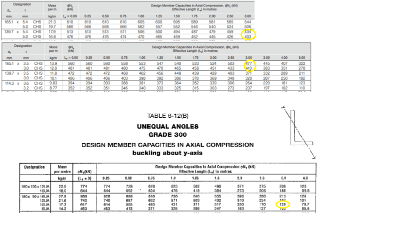
Using 150x90x10 reduces by around 68%!!
CHSandUAcapacities_yptsyl.png


That isn't something I'd be comfortable with unless I rechecked ALL the design loads.

Enable said:
Only thing I would add is that you cannot necessarily take the fact that current / past loading appears to have been rather low to mean that the system was not intended for higher loads, and therefore replace members with those of lesser capacity. In particular, I am thinking of seismic design events that may not have yet come to pass but should be factored into the design.

That said, I fully agree in this case being an industrial application the above is probably not likely and the angle idea is genius.
Beat me by 20s. [smile]

Just because it is an industrial application doesn't mean you shouldn't follow the code requirements and recommendations. While some mine sites in might be happy with engineers adopting less conservative approaches, in my dealings these types of structures that is unlikely to be the case.

And just a point here. This was listed as a stair tower so seismic loads (even in moderate to high seismic zones) are likely to be quite small due to low weight and high period. I'd bet my career that wind loads dominate for this type of structure. Given the type of bracing used this was either massively overdesigned or is quite tall and quite likely to be in a cyclonic region.
 
human909 I dont think SRE was saying to replace this only one element with one of lesser capacity should it not be under apparent load. I took him to mean that if this is more than a one-off, which it might be (if this brace is corroded like this it's good bet most are the same), then analyze the whole thing and don't pigeonhole yourself into the existing design. If it turns out an angle will work use that, but after a re-analysis. See him comment about replacing bracing all the way up.

If it's a one off quite clearly it's match existing!

EDIT - to be clear I like your take on the matter!

CWB (W47.1) Div 1 Fabricator
Temporary Works Design
 
Maybe I jumped in too hard. But a proposal that includes a brace that is 68% less capacity deserves a big red flashing warning sign.

That said if he said 150x12EA then I'd consider giving him a pink star.

In generally I do find that. EA and UA is rarely cheaper for compression members when you get to these larger sizes. However due to the short effective length EA is worth considering. In my own experience I normally go up to 125x8EA in compression. Beyond that I'm into SHS and CHS. But normally my effective lengths are at least twice as long and half as many.

EDIT
Enable said:
EDIT - to be clear I like your take on the matter!
[smile] [thumbsup]

EDIT2:
Enable said:
Pro-tip: when you are repairing structures you have to learn to be comfortable with doing all sorts of things where it's near impossible to put numbers to things. How much residual capacity exists? How much redistribution has gone on? What else has happened to the structure over time that may have put load where your otherwise think it wouldn't? Until you gain comfort with things, which usually only accumulates by doing the same repair many times over, it's always best practice to be as conservative as you can. In the scheme of things, a conservative shoring plan is peanuts compared to overall project cost and the shit storm that'll unfold if things go wrong.

That being the case, you should be conservative here and install temp bracing for both compression / tension loads
Just read this again. Seems in this aspect you are more conservative than me! Can't fault you for that. But like you say, the important part is that the person responsible has to be comfortable with the approach.


(A decent discussion regardless, gives the OP things to consider. This stuff is right up my alley so I've been in enthusiastically. Unlike many discussions where I'm busing googling terms like OWSJ!)
 
Wow thanks everyone for the responses (and encouragement :) ).

Enable, I may end up using your idea of welding a brace above the existing brace as it's what I'm most comfortable with. This wouldn't be an ideal method for when a brace is actually heavily loaded, would it? Since it would induce bending into the existing beam/column. In which case, a better approach may be to brace an adjacent bay? I ask because it looks like I've also been assigned to handle a brace replacement at the base of a large process structure. I haven't had a chance to look at the loads and load paths yet but I'm just thinking in advance.

"1) Perform brace replacement one at a time. Temporarily brace the bay being worked on with a pair of come-alongs and cables. Brace the bay by creating an "X" pattern with the come-alongs."
This is also great advice, SlideRuleEra. I'll keep it in mind for any future projects when I'm working with another structural engineer who can actually check my work haha.

"Only thing I would add is that you cannot necessarily take the fact that current / past loading appears to have been rather low to mean that the system was not intended for higher loads."
Yes I totally agree Human. I'm just going to replace the existing members with equivalent or stronger members.
 
Enable - Thank you for the compliment, constructive criticism about design loading and later the accurate explanation that my intent was explain to the OP that he has options and is not necessary forced to reproduce the original design.

human909 - No problem, no offense taken. I'll accept that I underestimated the maximum axial load that the angle can resist. For maximum axial load of any brace the OP may want to see what happens to the UB where the pair of chevron braces meet. In my job as Principal Engineer (Generation) for a mid-sized electric utility it was my responsibility to see that consultant's designs/construction management for new stations met requirements and that our in-house major repairs/modifications at the 24 existing generating units were adequate.

Details contained in codes come and go but we have consistently had pretty high requirement:
1) All stations are or would have been classified in IBC occupancy category III or IV.

2) Coastal South Carolina (USA) is subject hurricanes; we typically required stations to be designed for Category 4 wind speeds.

3) Coastal South Carolina is subject to occasional major earthquakes (magnitude 7+); our seismic criteria is similar to the high levels use in parts of California.

4) Unlike codes which usually have minimum requirements for life safety, our intent is to have the major generating units capable of full operation within a day or two of any design event.

I'll have to say I have never been "accused" of under designing anything... at least not on purpose.

NewGuy132 - Since you have decided to replicate the original design, I'll offer a suggestion. Have the CHS braces fabricated without bolt holes. Put the braces in place and field drill the bolt holes... it will save you a lot of grief later when predrilled brace holes don't precisely line up with holes on the structure.


Status
Not open for further replies.

Part and Inventory Search

Sponsor