Tek-Tips is the largest IT community on the Internet today!

Members share and learn making Tek-Tips Forums the best source of peer-reviewed technical information on the Internet!

  • Congratulations TugboatEng on being selected by the Eng-Tips community for having the most helpful posts in the forums last week. Way to Go!

Correctness of the gd&t symbol 2

Status
Not open for further replies.

nik007

Mechanical
Joined
Jul 25, 2023
Messages
2
Location
IN
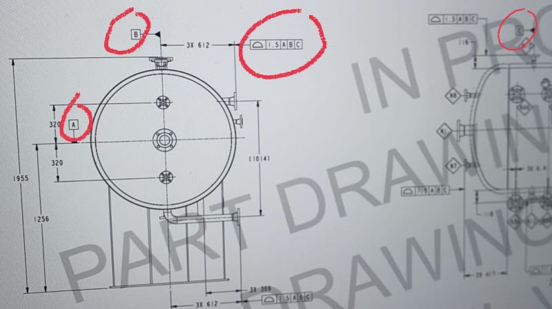
Can anyone please see if the profile tolerance given to the nozzle surfaces in the assembly drawing is correct? How can quality department check this one?
IMG_20230728_133940_vk4688.jpg
 
Datum feature symbols A,B and C are attached to centerlines, which is incorrect.
They need to be associated with physical features of the part by being attached to either surface outlines or size dimensions of features of size.
Otherwise, it is ambiguous which features are used to obtain the datums and the datum reference frame.
 
Hi, nik007:

Also, the profile feature control frame needs to be attached to the surface or the extension line of dimension "3 x 612". It should not be aligned with dimension "3 x 612".

Measuring profile of the surface is easy. What you need to do is to establish datum first based on physical features rather than phantom lines.

Best regards,

Alex
 
Whoever drew this doesn't know how datums work...
 
Status
Not open for further replies.

Part and Inventory Search

Sponsor

Back
Top