Eng-Tips is the largest engineering community on the Internet

Intelligent Work Forums for Engineering Professionals

  • Congratulations waross on being selected by the Eng-Tips community for having the most helpful posts in the forums last week. Way to Go!

Connections --- Surface to Surface or RBE's?

Status
Not open for further replies.

jacasalr

Materials
Feb 28, 2020
27
ES
Hello everybody,

I write this post because I am having some issues with a model of a (kind of) tank in Femap... I have divided the geometry in several parts so it is easier to get a good (Jacobian<0.6) mesh (a combination of hex and tets).

When I perform surface-to-surface glue function of Femap, the results are pretty good when I apply usual loads such as pressures, net loads on surfaces, etc. However, when I input a temperature (nodal) load (after performing a steady-state heat transfer study), the results that I have got are very disturbing, especially at those areas where there are (glued) connections.

I have read that a good option can be to use RBE's (2 or 3) to connect the pieces (solids) since they are able to accept a CTE in their formulation, resulting on joints with properties of the same material of the tank (and not being just rigid joints). However, I am quite new using RBE's and, despite I have read some articles from Predictive Engineering or Iberisa, among others, I have not been able to properly understand the use of these elements neither properly apply them into my problem.

If anyone could help me by explaining to me the right steps to make connections between solids by RBE's, and/or sharing your experience with structures with connections under thermal loads, I would be very thankful.

Thanks a lot in advance.
 
Replies continue below

Recommended for you

What does the interface really look like ? Is there a true surface-to-surface loadpath ? Are there 4? feet, fittings, supporting this tank ?

You may want to say out-of-plane loads are transmitted into the supporting surface but in-plane loads are reacted at the fittings.

another day in paradise, or is paradise one day closer ?
 
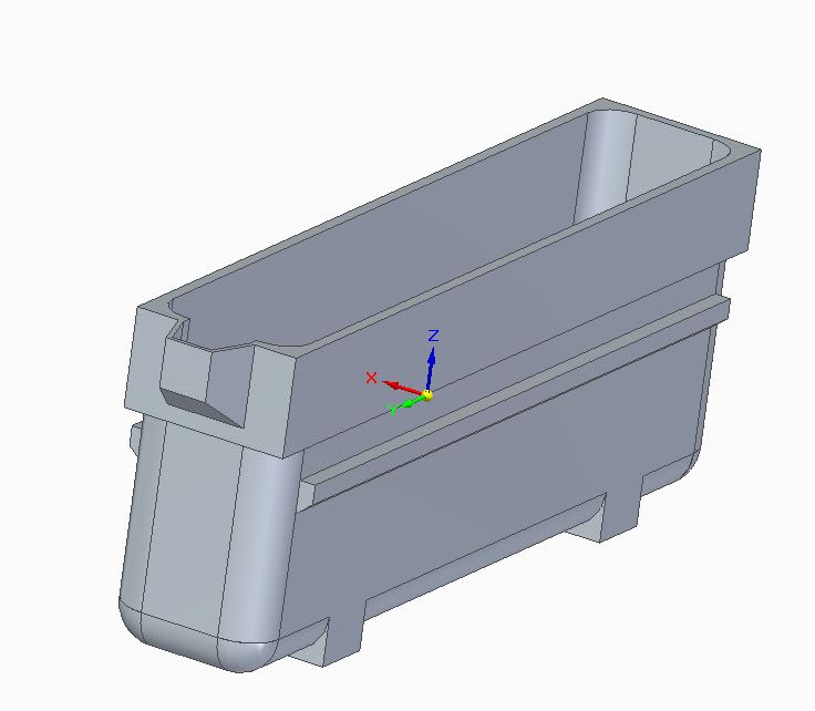
Definitely, it is better if I try to explain myself with an example (the file and images)... The geometry looks like the one in the next image:

Example_Tank_Geometry_vggsgv.jpg


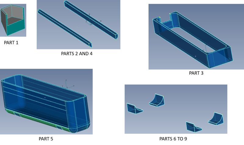
I divided it into 9 pieces by using Femap's slice function, so I was able to mesh the solid easily in a better way (Jacobian less than 0.7). Next figure shows the 9 divisions:

Divisions_lcbqbv.png


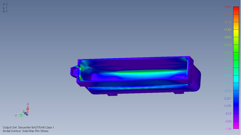
Then, If I connect all the pieces through the automatic connection function of Femap, and setting up a spring connection, I get the following results:

Max_Principal_Stress_No-Temp-Load_xiyoiy.jpg


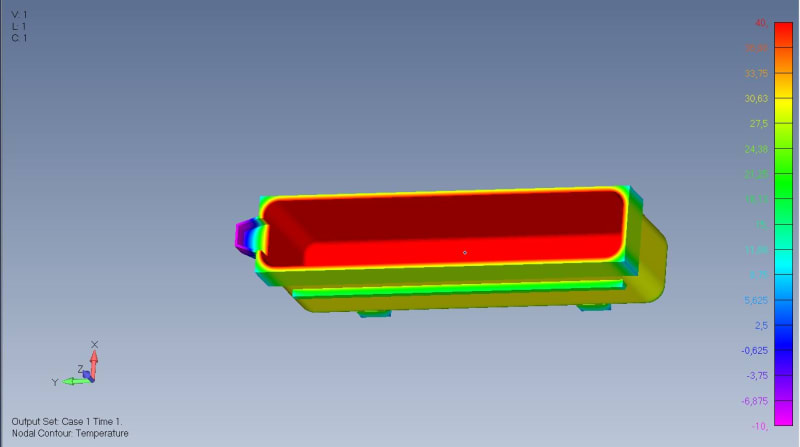
But then, if I apply a load temperature (first I run a Steady State Study and then apply a nodal load to the model):

Temperature_Distribution_odpnll.jpg


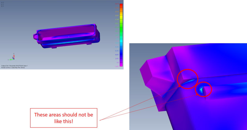
Max_Principal_Stress_With-Temp-Load_vzbqtw.jpg


It should be noticed in the last figure the areas enclosed within red circles in the zoom-image, which should not exist and they appear because of the definition of the surface-to-surface glue connection regarding to the Coefficient of thermal Expansion (CTE).

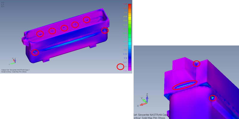
I have read that, by using RBE2 or RBE3 elements, I can input a CTE so this issue should be solved. However, when I try to implement this solution, I have no better results. The next figure shows the implementation of RBE2 elements in all connections but the supports (tank's legs, which are still connected by surface-to-surface glue connections). The pieces 1 to 5 are connected to each other by using RBE2 elements constrained at the three translational DOF's. The connections were made by using FEMAP's Custom Tool "Connect Nodes on Surfaces with Rigid Elements".

Max_Principal_Stress_With-Temp-Load_and-RBE2_lzlirt.jpg


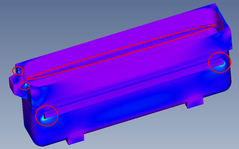
Even though when I choose the function "Spider Surfaces" from the Custom Tools menu, the software makes RBE2 elements (one for each pair of surfaces, total 4), but still results are pretty odd.

Max_Principal_Stress_With-Temp-Load_and-RBE2-Spider-Surfaces_z3qg2s.jpg


I have got to point out that when using RBE2 elements, I always activate the LAGRANGIAN option as Rigig Element Method at NASTRAN Bulk Data Options.

Even if I used RBE3 elements, results are pretty much the same and sometimes I have got errors related to double-dependence, since I have to admit that I do not know very well how to use RBE2 and RBE3 elements.

So, after all the explanation before described, my questions are summarized as shown below:

1) In this case, is there any way I could set up RBE2 and/or RBE3 elements in order to be able to properly represent the state of loads I am looking for (especially when adding temperature nodal load)?
2) In this case, is there any way I could set up surface-to-surface glue connections in order to be able to properly represent the state of loads I am looking for (especially when adding temperature nodal load)?

Any other comment/recommendation is well received!

PD: constraints used in the model are set-up as full constrained surfaces at the bottom of the supports (pieces 6 to 9), but that is to speed up the configuration of this model since it is an example. Normally, I used gap elements to prevent displacement at least in two of the three main directions, and then use the solver with the option "Gap as contacts".

If you need more information, please do not hesitate to text me.

Thank you very much in advance.
 
I'd make one solid (not 9) and mesh the b'jeppers out of it.

If you Really want to mesh different solids, then to make it simple to join pieces together, mesh the union (interface) surface on both parts with the same mesh.
Eg, for items 2 and 4 mesh the surface that joins with 5 with a specific mesh, say 3*30 (or whatever). Then on item 5 mesh the same region with the same mesh. Then these two pieces "should" fit together, check for co-incident nodes (yes?).

another day in paradise, or is paradise one day closer ?
 
Thanks rb1957!

I will try by meshing the connecting surfaces as you suggested before, since meshing a single solid would lead to a not good-quality mesh, unless refining too much locally.
 
I've had this problem before but couldn't exactly pinpoint why it was happening. In test cases with simple geometry and surface to surface glue contact I could never seem to get erroneous results at the interface. But with real geometry, I saw similar to what you were seeing.

One thing I did mess around with was switching the Glue type to "1..Spring" in the connection property definition dialog box. I believe Nastran sets glue type to 1 either way for thermal solutions. However when the type is set you 1, you can then set the Normal Factor (PENN in the BGPARM bulk entry) in the Femap dialog box.

"Solutions 153 and 159: PENT is ignored. PENN has
the units of 1/(length), and “conductance” at the glue
connection is calculated as
C = e*kavg*dA*100
where e represents PENN, kavg is an average of
the thermal conductivity (k) values for all source
side elements in a pair, and dA is area. A physical
interpretation is that it is equivalent to the axial
"conductance" of a rod with area dA, conductivity kavg,
and length 1/e."

It also looks like you might be able to hex mesh the whole part, you just need to do a little more slicing. There is no one answer on how many times to slice or which ways. You just need to make sure at all of the interfaces the surfaces are the same so when sizing the mesh, Femap will automatically link coincident surfaces.
 
Thanks TG_eng,

For thermal analyses I have not this problem. The issue arises when I have to perform a thermal stress analysis.

Anyway, I am trying to figure out hot to properly hex-mesh the whole structure.

I will let you know if I find a solution.

Thanks!

Julio
 
I ran other simulations with the same model but with small changes in its geometry. It seems that those small red areas are due to geometry and not to CTE or meshing issues.

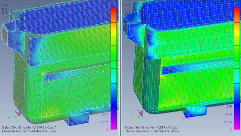
Abrupt changes in geometry, especially in some areas with a 90 degree change produce this red areas. The next figure show a comparisson between the same model with a tet mesh of element size 25 mm and a hex mesh of element size 50 mm. In fact, if I compare only the tet mesh but with element sizes of 50 a 25 mm, I realized that the highest stress in those red areas increased, which indicated me that it was a singularity, something similar to the article:
Comparisson_Max-Princi-Stress_Tet25vsHex50_h86whx.jpg


It seems that I have to live with those singularities, especially when the design has those abrupt changes in geometry. Fillet those sharp corners would lead to bigger meshes and those small fillets and diameters are not 100 % identical to the ones presented in the real structure, so I guess that, in this case, it is better to neglect stresses in those areas, especially taken into account that the loads on the structure are static.

Thank you very much anyway to all of you guys, your opinions are very valuable to me.

Kind regards,

Julio
 
Dear Julio,
Try to reduce the use of rigid elements RBE2 or RBE3 as much as possible, only when not other method exist, better use GLUE Surface-to-Surface condition when available.
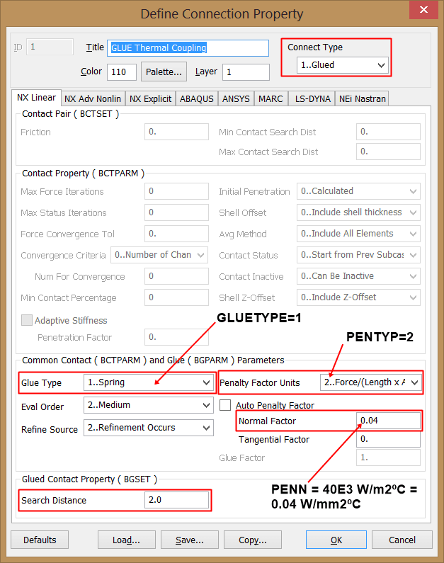
In this post I show how to control the parameters of the GLUE condition to deal with thermal contact properties, you will learn to play with GLUE types and penalty factors:

glue_thermal_contact_tlz4sp.png


Also, in FEMAP is very important to have the best quality mesh when meshing with 3-D Solid CHEXA 8-nodes elements to avoid strange stress results, take a look to my video:

hex-mesh-eje-miniatura_hhhza9.png


Best regards,
Blas.

~~~~~~~~~~~~~~~~~~~~~~
Blas Molero Hidalgo
Ingeniero Industrial
Director

IBERISA
48004 BILBAO (SPAIN)
WEB: Blog de FEMAP & NX Nastran:
 
Blas,

Great example and thank you for sharing. What is the "target value" you are looking for? And how did you determine this? I'm referring to the following sentence and later when you define the normal factor to 0.04. "Multiplied by e (PENN), this is e* kavg = 100*0.10838 = 10.838 W/m2ºC, which is almost 300 times bigger of the target value."

Thanks in advance.
 
this is one big a$$ tank, if the mesh size is 50mm.

I think you have a mesh problem, with a sharp 90deg corner. Is this what you'll have in practice ? Surely (?) there'll be some corner rad ?

The other approach would be this indicates very localised plasticity, which may not be the end of the world. You're running linear FEA ? What material ?

another day in paradise, or is paradise one day closer ?
 
Dear TG_eng,
Thanks for commenting.
"Target value" means the Surface Contact Thermal Coupling value defined at the beginning of the problem, is a know data, is directly the Heat Transfer Coefficient of the thermal contact coupling, precisely the target of this FEMAP tutorial is learn how to enter this value in the definition of the problem using the GLUE surface-to-surface condition:

Heat Transfer Coefficient = ksolder * Asolder / (Lgap * Achip) = 80*0.5/ 0.001*1 = 40e3 W/m2ºC = 0.04 W/mm2ºC

But you are correct, revising the page I note I made a mistake in units, where I say "e* kavg = 100*0.10838 = 10.838 W/m2ºC", the correct one must be "e* kavg = 100*0.10838 = 10.838 W/mm2ºC", the eternal problem with the units!!. The exact ratio is 10.838/0.04 = 270

But this value is not used in the analysis as I suggest to use the second method:

"For simplicity, I suggest to use always GLUETYPE=1 and PENTYP=2, which allows you to directly specify the conductance via PENN, having the units of (Thermal Conductivity*Length)/Area. Thermal Conductivity in SI has units of W/mºC, thus PENN has units of W/mm2ºC, i.e., directly the value of the Heat Transfer Coefficient of the Thermal Coupling."

Best regards,
Blas.

~~~~~~~~~~~~~~~~~~~~~~
Blas Molero Hidalgo
Ingeniero Industrial
Director

IBERISA
48004 BILBAO (SPAIN)
WEB: Blog de FEMAP & NX Nastran:
 
Hi Blas!

Thanks for your reply! Definitely, you are right about trying to avoid using RBE2 and RBE3 unless extremely needed (BTW, could you tell me a case when this is totally needed?). I tried to solve this problem by using RBE's, Surface-to-Surface Glue connections, one single body TET mesh and finally, multiple bodies HEX mesh and then joining the mesh at coincident faces. By all these means, the red zones are still present, event with different mesh sizes. I came to the conclusion (hopefully a right one) that these red areas should be because of the geometry, especially when abrupt changes are happening like 90 degrees transitions.

I had already viewed the video about the S2S Glue Connections to analyze thermal problems. I tried to use this type of connection playing a lot with the pennalty factor but could not get to any good result which would not show me red areas. Actually, that video shows how to properly use that function to analyze heat transfer problems, but, is there any way to use it properly to study thermal stress problems?

Regarding to the second video, thanks a lot, I have not seen that one until now and gave me many good tips to obtain a good quality hex mesh. In this problem I was able to obtain a good quality hex mesh as well as a good quality tet mesh, especially at the red areas. Since there were still red areas, I came to the conclusion that the problem was not due to the mesh quality.

I ran out of options and that was why I came to the conclusion that in this case the problem is due to geometry.

I guess that my option is to neglect these red spots and extract the maximum stress value from the remaining structure, despite this will take longer that just showing the automatic results after processing and, of course, I will not be able to optimize the results automatically by means of, for instance, reducing thicknesses.

Thanks again, Blas!
 
Thanks for your reply rb1957!

The material is polymer concrete, let's say it is a brittle material, so no able to discard red areas due to plasticiy.

The tank I posted here is just an example, there are multiple designs are yes, they are big but maybe no so much.

Normally, I meshed them by means of tet elements, since they normally have some geometries that make the hex-mesh process very annoying or impossible. This example is quite simple, and I made it that way in order to be able to mesh it both with tet and hex elements in order to compare the results, and to check if the red areas were due the type/size of elements; however, the red areas where always present indepently of the type/size of elements.

Dependent on the tank design and size (they go from 1.5 to 3 meters internal height; 1 to 2 meters internal width; and 4 to 15 meters internal length) normally I have to use mesh sizes between 50 to 15 mm and the meshes go from 300K to 1500K tet10 elements. As I said before, I normally use tet meshes since it is too much complicated to mesh with hex elements on the most of the desings.

In practice, real geometries have many places with these abrupt 90 degrees changes on geometry, and maybe you would see some small radius but they are present mainly for aesthetic reasons or are too small comparing to the geometry that I decided to remove them from the model to avoid abrupt changes on mesh size.

Thanks again, rb1957!
 
Hello!,
Post your FEMAP model and I will take a look to it, without the model in hand is difficult to know the reason of the stress concentrations.
Best regards,
Blas.

~~~~~~~~~~~~~~~~~~~~~~
Blas Molero Hidalgo
Ingeniero Industrial
Director

IBERISA
48004 BILBAO (SPAIN)
WEB: Blog de FEMAP & NX Nastran:
 
HI Blas!

Thanks again for your reply and for your willing to help. There is the file. I had to make it again because I was only allowed to upload up to 20 MB files, so this file contains the geometry, material, property, loads and constraints, but not the mesh (even thought it is ready to be meshed with hex elements) nor the results, since the file would have resulted bigger than 20 MB.

Within loads "static" there are 2 loads: HP and Vertical. There should be one more load corresponding to the thermal load resulted after obtaining the temperature distribution from a steady state thermal analysis (which is already set up as "Thermal"). Normally, I run this thermal analysis and then insert a thermal load from Model> Load > From Output. In this case, there is not thermal load within the "Static" Load Set since I have not run yet the model since there is no mesh because of the file size.


Thanks again Blas, and I look forward for your reply.
 
Dear Julio,
OK, I will take a look to it when I have a free time, no problem. To share FEMAP models better use www.wetransfer.com, is free till 2 GB, then plenty of space.
Best regards,
Blas.

~~~~~~~~~~~~~~~~~~~~~~
Blas Molero Hidalgo
Ingeniero Industrial
Director

IBERISA
48004 BILBAO (SPAIN)
WEB: Blog de FEMAP & NX Nastran:
 
Dear Blas,

You are right, I do not know why I did not do it before. Here you can find 2 donwload links:

---- The same model (but all the geometry as one single body) with a tet mesh and results.

---- The same model with a hex mesh and results.

Thanks a lot, Blas!
 
Dear Julio,
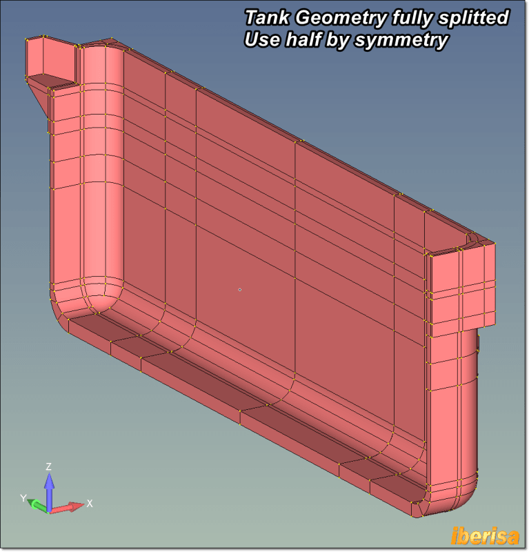
I have sliced the tank geometry, by symmetry simply use half geometry model, and half loading, of course!:

tank1_wn7wzl.png


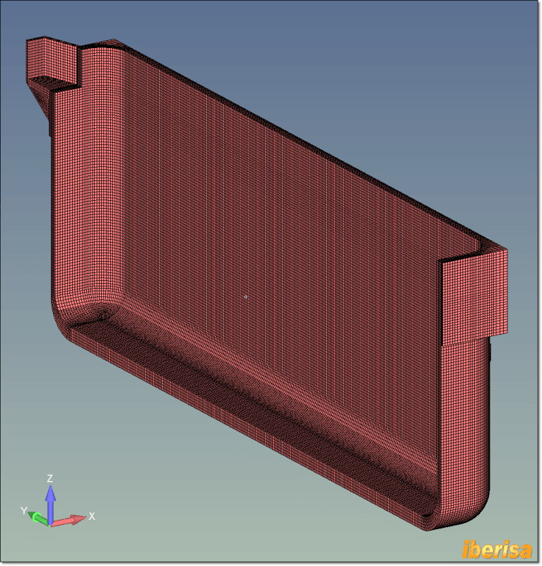
The model size is less than 275000 nodes, with a minimum of 5 elements in the wall thickness:

tank2_fwd8do.png


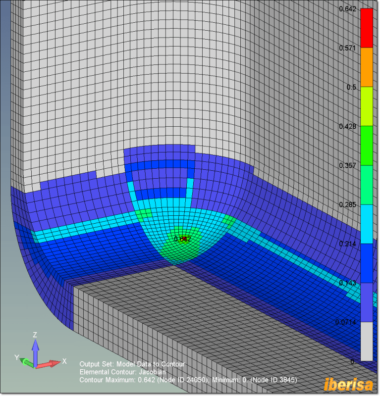
Some meshing details in the corners:

tank3_iwcmff.png


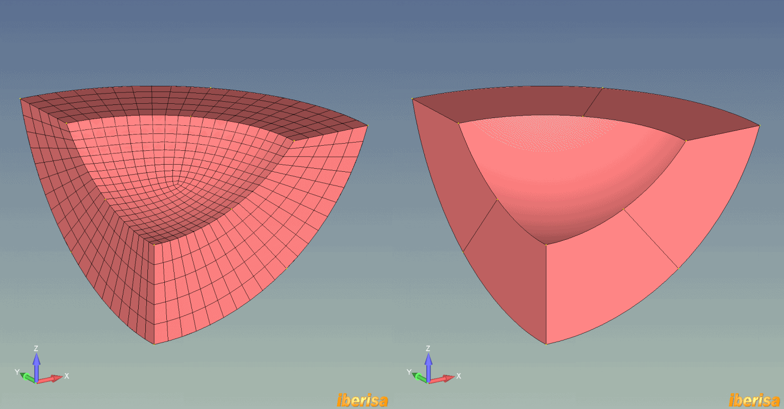
The key is simply imprinting curves in the middle of surfaces like shows the following image:

tank4-animated_e0bms4.gif


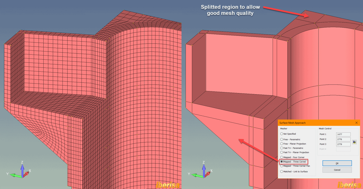
Also another interesting region, please note the meshing approach used here: MAPPED - THREE CORNER

tank5-animated_sb1uoa.gif


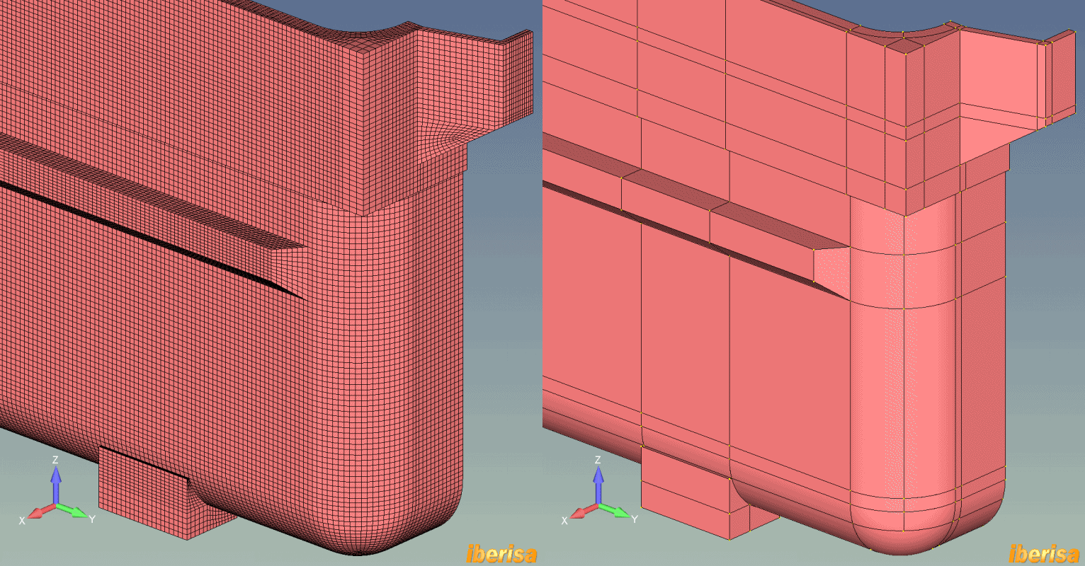
And the following image shows the mesh & geometry in the back side:

tank6-animated_ykigew.gif


The following pictures shows the displacement results under the static loads:

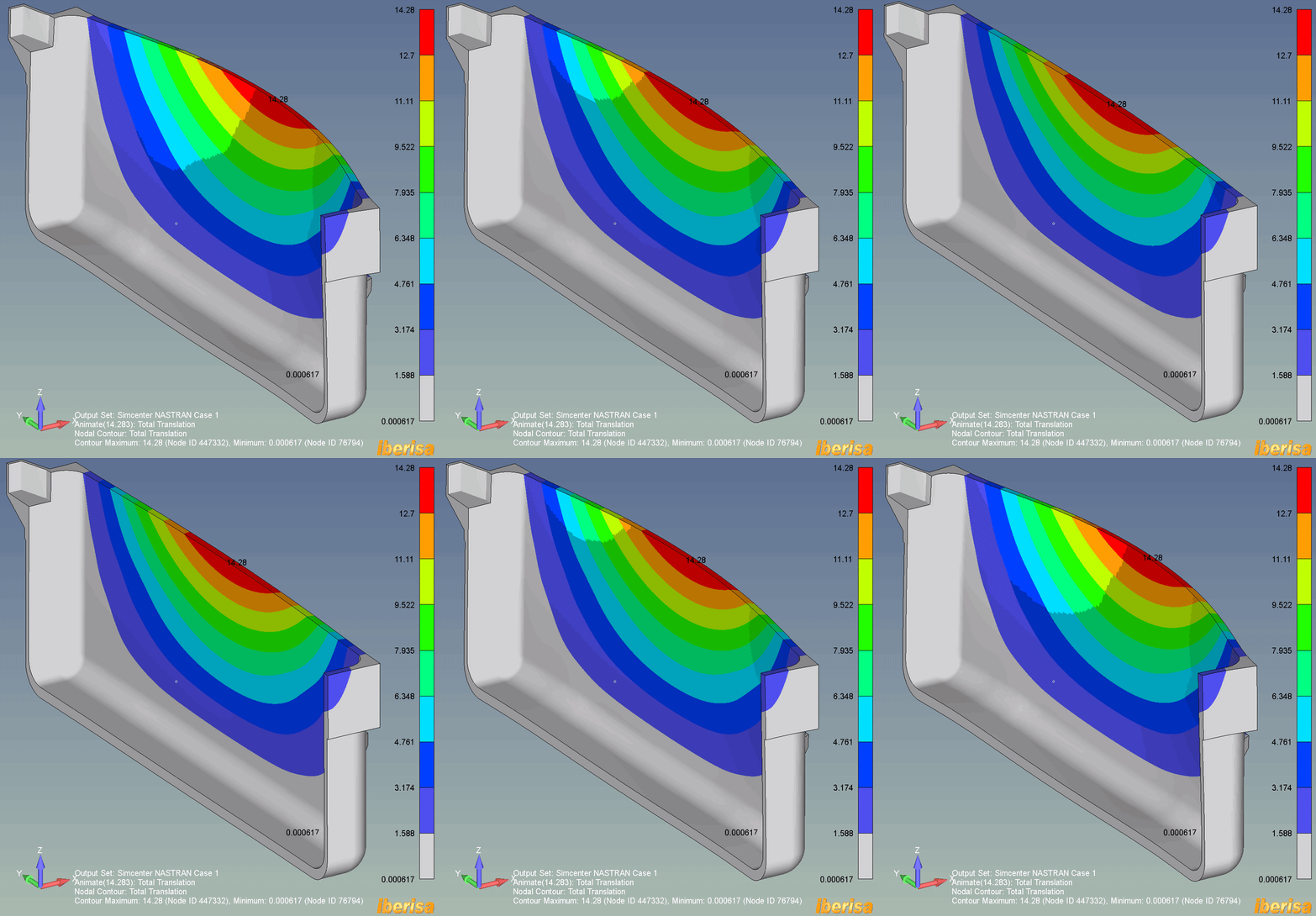
tank7-ures-animated_ffaxzc.gif


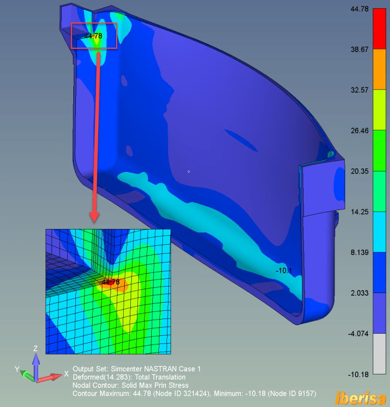
The following picture shows the Maximum Principal Stress at traction (MPa) in the tank under the static loadings: the source of stress concentration is the geometry, the sharp corner causes a big stress raiser in that zone. Make a suggestion to designers to eliminate the sharp transition is geometry there.

tank7_znfwwa.png


Best regards,
Blas.

~~~~~~~~~~~~~~~~~~~~~~
Blas Molero Hidalgo
Ingeniero Industrial
Director

IBERISA
48004 BILBAO (SPAIN)
WEB: Blog de FEMAP & NX Nastran:
 
Dear Blas!

Thanks a lot for your reply, you've given me really good tips to hex mesh this kind of geometry.

The symmetry tip is also very good, thanks! I have applied some times but in some cases I cannot apply symmetry since the loads are not symmetric (when applying seismic loads to only one wall, for instance).

I have some questions:

1) How do you show the rest of the elements in grey?
2) How do you supress the supporting legs from the contour visulization? Do you place those elements within another layer and then you don't show that layer?
3) Did you apply the thermal load (60 Celsius internal surfaces and a convective load in the external surfaces) or only the hydrostatic pressure and the vertical load?
4) What about the results in the exterior such as the next image? Are there localized stresses (maybe less magnitude than the internal one that you showed in the last post)?


5) Extra question: Sometimes I used gap elements only in compression to support the geometry under its four supporting legs. This is mainly to avoid red localized areas in the bottom surface of the supporting legs since sometimes they go up after loaded and the vertical constraint avoid this movement and then tensile stresses appear in this areas. Is this a good practice or shall I not apply it?

Thanks again for all your help and time, Blas.

Kind regards,

Julio
 
Status
Not open for further replies.

Part and Inventory Search

Sponsor

Back
Top