Continue to Site

Eng-Tips is the largest engineering community on the Internet

Intelligent Work Forums for Engineering Professionals

  • Congratulations cowski on being selected by the Eng-Tips community for having the most helpful posts in the forums last week. Way to Go!

composite tolerance at lmc : is it nonsense?

supergee

Mechanical
Aug 15, 2012
80
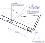
I was trying to think of a practical use of LMC when I realised that, though it is not forbiden in ASME y14.5 2018... it doesn't seem to make sense... at least with a patter of holes. The LMC enable one to have bonus tolerancing when material departs from LMC. one cannot increase that bonus further. am I right to understand that?? here is an example. (please disregard that the holes are threaded... it's beside the point here) the only thing that would make sense, if allowable, is a multisgment positionnal tolerance right?
1745964237886.png
 
Replies continue below

Recommended for you

Typically (L) would be applied to bosses or other external features. Unfortunately there is no hard gauging element that can interact with an LMC boundary.
 
There is one weird case for LMC on a hole. Picture an oil drain port. You want to ensure that the largest hole never exceeds the matching hole in the gasket and vice versa. The smaller the hole the more the hole can wander around and the oil will remain constrained to the confines of the LMC.
 
Our Compressor department frequently uses LMC on cast aluminium parts where minimum wall thicknesses are needed. Other than that, I don't know much practical use for LMC. Can't gauge it, hard to comprehend to most engineers. It wasn't even taught in our school too.

Btw I see "Composite" in the title, but there aren't any on the drawing. You meant "Position" right?
 
I am not sure about what exactly doesn't make sense.
Does it not make sense functionally or from some other reason?
"The LMC enable one to have bonus tolerancing when material departs from LMC. " - yes.
"one cannot increase that bonus further." - further after what?
I'd say there is rarely a reason to give a location bonus as the hole gets smaller but there are some situations. The one being mentioned mostly is the function of preserving wall thickness.
Note that in a pattern, the bonus (adjustment of the size of the tolerance zone per the feature's actual size) applies to each feature individually.

An unrelated point - I would not associate a profile feature control frame with a size dimension the way you did. If the intent is to control the width of datum feature E by profile, make .250 basic, separate the profile FCF from the dimension, place 2X above the FCF, and extend two leaders from it. What you show may look cleaner, but with few exeptions associating an FCF with a size dimension without any leaders to surfaces, implies a control of a theoretical center.
 
An application used in my industry is pneumatic or hydraulic communication holes in parts when you need to control minimum wall thicknesses between features. As the holes get smaller they can have larger positional tolerance. In these cases you are not concerned with part mating. Perfect form at MMC is no longer in effect though when LMC is specified in the feature control frame tolerance.
 
I was trying to think of a practical use of LMC when I realised that, though it is not forbiden in ASME y14.5 2018... it doesn't seem to make sense... at least with a patter of holes. The LMC enable one to have bonus tolerancing when material departs from LMC. one cannot increase that bonus further. am I right to understand that?? here is an example. (please disregard that the holes are threaded... it's beside the point here) the only thing that would make sense, if allowable, is a multisgment positionnal tolerance right?
I don't see the point of specifying any material conditions on tapped holes. Tapped holes centre their fasteners, and they are pretty accurate anyway.

I used LMC on a casting I was designing. There were two holes in the casting that were to be accurately machined out. I was concerned that Least Material Condition not impinge on the final machined holes. LMC can be used to assure wall thickness next to a large hole.
 
"We apply Least Material Condition (LMC) to castings to provide the supplier with additional tolerance for bores that require machining. Since our priority is Maximum Material Condition (MMC) to avoid non-cleanup on bores, a smaller bore ensures more cleanup. Therefore, we allow the position to float more when the Feature of Size (FOS) is at LMC."
 
LMC protects material, like a minimum wall thickness. It makes a lot of senses. This is math behind ASME Y14.5 standard.
 
By default tolerances of location applied to threaded feature apply the axis as derived from the pitch circle (diameter). Since the variation of pitch diameter of a 8-32 unc thread is about 0.0015 (verify) the "Bonus" tolerance at LMC is minimal

Assuming that there is actual logic in this specification as opposed to just a misunderstanding...

The intent would seem to be controlling the Major diameter via. the pitch of the threaded feature relative to the thickness which could be to control the minimum wall thickness.

The inspection process is tedious, the specification is marginal and the design should be rethought out...
 
OP:
"(please disregard that the holes are threaded... it's beside the point here)"

Everyone else:
disregards the written message and only addresses what they see in the picture.

OP, don't ever do that. If you attach a picture make sure that what's in that picture corresponds to the intent of your question without any terrible distractions.
 
Our Compressor department frequently uses LMC on cast aluminium parts where minimum wall thicknesses are needed. Other than that, I don't know much practical use for LMC. Can't gauge it, hard to comprehend to most engineers. It wasn't even taught in our school too.

Btw I see "Composite" in the title, but there aren't any on the drawing. You meant "Position" right?
There is no composite in this drawing because I couldn't figure out a logical use for it, hence the question.
 
OP:
"(please disregard that the holes are threaded... it's beside the point here)"

Everyone else:
disregards the written message and only addresses what they see in the picture.

OP, don't ever do that. If you attach a picture make sure that what's in that picture corresponds to the intent of your question without any terrible distractions.
The reason I asked to disregard that the hole are threaded is that this picture is from a student homework in my gd&t class. I asked the studends to create a series of geometries on a part that would require different gd&t concepts: LMC, composite tolerances, multi-segments tolerances, profile of surface etc...

I am aware of the limits of usign LMC on a threaded hole, as it is not possible to gage such a feature. I am also aware that using profile of a surface with a non basic dimension makes no sense. As for the use of MMC on a threaded hole, I am also aware that threaded hole are self centering and have to added clearence once tightened. But not using MMC implies usign the actual mating enveloppe when inspecting (expendable thread gauge) which is expensive and rarelly (if ever) usefull.

But I was confronted by that scenario where a pattern of a hole is required to hold an other part in place with a somewhat larger tolerance, while maintaining the ability to assemble. usually, this is done with a composite tolerance. The added difficulty is that the hole is made on a thin sheet metal plate.

I was trying to figure out if composite tolerances is usefull in such a case, when I think I realised that using composite with LMC is not usefull since the upper segment value is the positionnal error leading to barely enough material. This being said, what would the lower value be? I can't find any logical answer to that question. I wanted to confirm with the community of talented people on this forum that I did understand correctly.

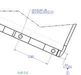
In order to remove some of the confusion, I have modified the drawing removing the threads and added 3 scenarios of plausible way to dimension the part. Hopefully It will be less of a distraction.
1746117064325.png
 

Part and Inventory Search

Sponsor