Continue to Site

Eng-Tips is the largest engineering community on the Internet

Intelligent Work Forums for Engineering Professionals

  • Congratulations 3DDave on being selected by the Eng-Tips community for having the most helpful posts in the forums last week. Way to Go!

Composite Anisotropy

Casilero

Aerospace
May 26, 2025
13
A question for those interested in composite panel buckling.

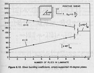
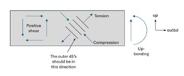
It has been a curiosity as to why edge shear on a typical panel or structure is generally treated as a positive value or magnitude. It seems to be a practice and for metallics, it would be reasonable to assume that as metal is more a less isotropic, then behaviour is reversible. However, a panel subject to diagonal tension across one diagonal caused by shear alone, then reverse the shear direction (e.g. a wing in twist reversal), the buckling mode can differ and the buckling and post buckling capability can be quite different. Sol 106 Buckling I think looks after all this I think in reality. But in the pencil days , it did not.

Add to this, composites as a material. The sensitivity to the direction of shear could be quite profound.

Recently while bench mark testing a new buckling and laminate strength analysis program, I was given the task of verifying the tools simulation results against physical tests conducted by NASA in the 60's as sort of bench mark studies, for balanced composites and unbalanced composites and single curvature panels. The tool did not accept the negative shear value to represent load reversal but the geometry of the test simulation could be reversed so the loads were for all effective purposes be reversed. The result were some what unexpected and might have implications for composites. It was possible to see major differences in behaviour in panel buckling capability especially for low ply numbers. Even some high ply layups up around 20 ply, ocassionally there were substantial differences.

There is a tendency when setting up the loads going into sol 106 to simply put in the magnitude of the shear and not the direction. Sol 106 will take negative shear.

Has anybody actually encountered practical implications from this simplification of shear direction and buckling.
 
Replies continue below

Recommended for you

IDK enough to be very sensible but it sounds like something to me. Can you play with the material directions to effectively flip the shear direction ?
 
composites data from the 1960's is likely suspect, at best.

NASA published lots of composite buckling reports in the 1990's and 2000's.

Yes, you are correct, the sign of the shear load matters for a composite laminate using tape materials, because the bending stiffness is not the same in the +45 and -45 directions. If you use FEM, you need to apply both shear load directions. Or possibly extract both +ve and -ve eigenvalues.

The composite panel buckling tool that I wrote decades ago calculated separate buckling load for + and - shear.
 
Yes, and what you have noticed is what makes the difference between "orthotropic" and "anisotropic" analysis. In the bending stiffness matrix, the bend-twist coupling terms D16 and D26 make the difference. When D16 and D26 are not zero, the D matrix is "fully populated" and referred to as anisotropic. When D16=D26=0, the behavior is called orthotropic (or "specially orthotropic"). Many composite analysis tools and handbook formulas are based on the orthotropic assumption because solving the fully anisotropic problem is more difficult. I presume the manual for the tool you are using should mention that when it describes its theoretical basis. Even if it is only a brief description, the term "orthotropic" plate theory would be a dead giveaway that it is neglecting the D16 and D26 terms in the buckling analysis.

Your studies have also revealed when these effects might be important. In a symmetric 4-ply laminate consisting of (+45/-45/-45/+45) they will be significant. But in a 24-ply symmetric laminate with [ (+45/-45)12 ]sym they will be much smaller. On the other hand, the effects will be significant for a 24-ply symmetric laminate with all the +45 and all the -45 plies stacked together (that is: [ (+45)12 / (-45)12 ]sym. That is another reason that it is good practice to disperse the different ply angles rather than clump like plies together.

To get an feeling of how different layups affect the magnitude of these terms, all you need to do is to compute the ABD matrices for a variety of laminates, you don't need to do the full FEA run. Look at the D16 and D26 terms and see how large they are in relation to D11 and D22. Michael P. Nemeth (NASA) uses two non-dimensional "anisotropic parameter" called gamma and delta to quantify these effects. (e.g. see his paper "Importance of Anisotropy on Buckling of Compression-Loaded Symmetric Composite Plates" AIAA Journal, Vol 24, No 11, Nov 1986. although has has many similar papers on the NASA Technical Report Server).

Robert M. Jones also has some discussion along these lines in his book "Mechanics of Composite Materials". See Chapter 5, Bending, Buckling, and Vibration of Laminated Plates.
 
one more thing I should have added...

An for any given laminate, if you interchange the +45 and -45 plies, you will change the sign of the D16 and D26 terms, but not the magnitude. Again, looking at the ADB matrices of lots of sample laminates should be instructive.
 
I found this figure in the book "Structural Analysis of Laminated Anisotropic Plates" by James M. Whitney, Technomic, 1987 (page 155)

It shows the difference in buckling load under positive and negative shear loads for [(+/-45)n]sym laminates. The difference becomes smaller as the number of plies increases, as long as the plies are interspersed and not lumped together. As mentioned previously, that is because the D16 & D26 terms are getting smaller relative to the D11 & D22 terms as more plies are added.

I presume that the average of the positive and negative buckling loads corresponds to what the "orthotropic plate theory" prediction would be, although I don't have the numbers to check that.
 

Attachments

  • Whitney_Figure_6-12.jpg
    Whitney_Figure_6-12.jpg
    346.8 KB · Views: 4

Related.

I found a few texts on this subject were helpful.

Composite Airframe Structures, 3Ed Michael Chun-Yung Niu

Composite Materials for Aircraft Structures (AIAA)

Design and Analysis of Composite Structures (AIAA)

SAE PT-200 Damage and Repair of Aerospace Composite Materials

SAE PT-202 Material and Process Modeling of Aerospace Composites


SAE R-461 Care and Repair of Advanced Composites, 3ED

SAE AIR5367 Machining of Composite Materials, Components and Structures

**You also might gain more traction with this question re-posting it on the Materials/Composites forum... https://www.eng-tips.com/forums/composite-engineering.327/
 
Just a short update, the laminate analysis programme that launched this negative shear issue is fully anisotropic with D16 and D26 non zero values.
At the time of using it some months ago, the absence of the negative shear option became apparent for D16 and D26. It seemed that the shear sign was squared somehow or the coding was incorrect. I requested it be updated. The laminate analysis tool carries out buckling modes and graphically displays them in 3D alongside the ABD values and all these parameters can be varied quickly so that the consequences of ply stacking and D16,26 values can be assessed quickly.

All the references provided by persons responding are very helpful. The benching marking studies I refer to above were based on RM Jones, Whitney's work, and Mandell's reports which the latter looked at non symmetric and non balanced layups in a test campaign. It was difficult to mimic Mandell's test data from the material properties provided.

The remaining question is to ask if anybody has created or is aware of practical applications where this could be critical. That is that negative shear direction in a practical layup, say n>12, could be critical? (I was able to artificially create one using a ridiculous mix of 45's that would not be found in reality)
 
Yes, there are spar or rib webs with a large percentage of 45 and -45 plies where the difference in D16 and D26 can be critical, if load cases are not fully reversed.
 
I believe the effect can be minimized by using fabric plies instead of tape (recall SWC said the effect matters for TAPE materials). In a laminate made of tape plies, a given +45 ply is balanced by a -45 ply, but they are at different distances (in the z-direction) from the mid-plane. Being balanced will make the A16 & A26 terms zero, but not the D16 & D26 terms. Fabric plies are often modeled with equal moduli in both directions, that is E1=E2. So a fabric ply at +45 is essentially a +/-45 pair at the same z-location. This results in D16=D26=0 and therefore no difference in buckling with sign of shear. (Confirm with your tools).

If the loads are not reversible, and you have to use tape, then you should pay attention to which direction you put the +/-45's. Resolve the shear into tension and compression and put the outermost 45's in the compression direction. For the example of a wing spar mentioned by SWC, the shear in the up-bending condition would be larger than the down-bending condition. I have attached a sketch showing the direction I would put the outermost 45's in such a web.

This gets back to what SWC originally said, quote: "Yes, you are correct, the sign of the shear load matters for a composite laminate using tape materials, because the bending stiffness is not the same in the +45 and -45 directions. " Michael Niu shows this difference in bending stiffness pictorially in Fig. 7.1.3 of his book "Composite Airframe Structures" which I have also attached.
 

Attachments

  • Niu_Figure_7-1-3.jpg
    Niu_Figure_7-1-3.jpg
    154.9 KB · Views: 2
  • shear_web.jpg
    shear_web.jpg
    46.6 KB · Views: 2
"It seemed that the shear sign was squared somehow or the coding was incorrect. I requested it be updated." ... oh, so this was inhouse code that raised this issue ?

as for criticality, I imagine that'd depend on the magnitude of the D16, D26 terms ... on how anisotropic the layup is. It feels to me like thin layups are more sensitive than thick ones.
 

Part and Inventory Search

Sponsor