Continue to Site

Eng-Tips is the largest engineering community on the Internet

Intelligent Work Forums for Engineering Professionals

  • Congratulations The Obturator on being selected by the Eng-Tips community for having the most helpful posts in the forums last week. Way to Go!

Circlip resistance calculation

Faroukpin

Mechanical
May 22, 2025
3
Hello
I'm designing a stainless steel hinge with bronze bushings, and I've chosen to secure the pin using two E-type circlips.
I would like to know if the circlips can withstand the loads (which I don't know how to calculate).

I would like to create a calculation note to verify whether my design solution is suitable.

Could you help me, please?

Here are the conditions.

1747927445937.png
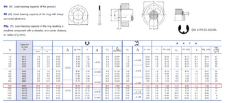
Here are the allowable forces specified by the circlip manufacturer.

1747927714446.png
 

Attachments

  • 1747927680192.png
    1747927680192.png
    293.4 KB · Views: 3
Replies continue below

Recommended for you

I can't understand how your hinge is supposed to work.

What are the orange parts?

Where is the pin?
 
The axial load on a typical door hinge pin is very close to zero. I have a door where the hinge pin defies gravity and moves up. It takes about 10 years to get to where it looks like a problem.
 
Why do you suppose there is any meaningful load on the circlips?

EDIT: And why are you not just buying hinges?

Regards

Mike
 
100kg is pretty heavy for a door. I agree determining the axial load on these pins is very nebulous, but
1) why not an off-the-shelf hinge ?
2) are a hinge producer make you a custom one (if you feel your needs are special) ?
3) just drop a bolt in, as a pin (what would cause the pin to migrate upwards significantly ?)
4) is there some security issue (like you don't want people to tamper with it) ?
 
Ok, so the orange parts are the bronze bushings.

You understand that only one of them is in the load path, right?

I still don't see a pin.
 
Hello and thank you for your responses
I'm trying to explain my need.
What I'm interested in is whether there are forces on the circlips that could make them pop off.
The leaves, the pin, and the self-lubricating bushings will not be on the study.

Here is my reasoning:
The moment created by the weight of the door will generate forces that I want to calculate.

There is a gravitational force, and when I transfer that force into the hinge (shown in red),
and if I break down the moment transferred into the hinge, I think there will be two components, F1 and F2 (in green).

Is my reasoning correct?
And how can I calculate this force?

Thank you

Capture d’écran 2025-05-23 090341.jpg1747991648308.png1747992259594.png
 
Two comments/questions:
1. The Circlips (called retaining rings by us old farts) should see ZERO load from the door! The hinge itself should absorb all that load. Your hinge pin should be designed so that the distance between the clips is slightly longer than the distance from top to bottom of the hinge.
2. Why are you even designing a hinge? There are SO MANY variations available on the market! If there is some reason that none of them would work, what is it?
This is a request I received: we need a hinge that can support heavy loads and withstand 100,000 cycles.

I planned for some clearance for the circlips, but I haven’t defined it yet.

I wanted to know if the solution would work before moving forward with the design.
I can't use a bolt, a pin with a head is more expensive, and welding the pin is not very aesthetic. and Using a dowel pin is also more costly.
 

Part and Inventory Search

Sponsor