Yes, it appears that the biggest difference, longitudinally, is the distance between the main pylon and the abutments but that portion of the span where the cables are actually attached appears to be very nearly symmetrical with the possible exception of the first two cables on the far Left in
Ingenuity's longitudinal diagram, however I'm not sure if the difference is enough to be significant. BTW, does anyone know if the rupture took place, relative to
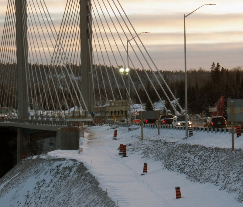
Ingenuity's longitudinal diagram, at the Left or Right end of the span? From the picture earlier in this thread, if the rupture were at an abutment, which would seem logical, it would apepar to be the Left end of the bridge.
Again, I think it will be determined that with this style of bridge, cable-stayed, that the difference in the lengths of the cables and thus the difference in the absolute contracting/shortening of the individual cables due to extreme cold temps, one can clearly see from looking at
Ingenuity's longitudinal diagram how it is that this could cause the roadbed to bow up at the ends due to the uneven stress in the cables creating a bending moment in the structure of the span.
John R. Baker, P.E.
Product 'Evangelist'
Product Engineering Software
Siemens PLM Software Inc.
Digital Factory
Cypress, CA
Siemens PLM:
UG/NX Museum:
To an Engineer, the glass is twice as big as it needs to be.
![URL]](https://res.cloudinary.com/engtips/image/fetch/w_800,c_lfill,q_auto,f_auto,g_faces:center/[URL unfurl="true"]http://hi-tecdesigns.com/images/pictures/Footwell%20Animation%20Tiny.gif[/URL])