Hello All,
I'm new to this forum. Have found it very useful over the years so finally decided to join!
I have a problem to get to the bottom of and would like a hand to ensure I get the correct answer.
We have a construction application (Side-Grip) which is used to drive steel into the ground. I'm trying to establish the clamp force generated.
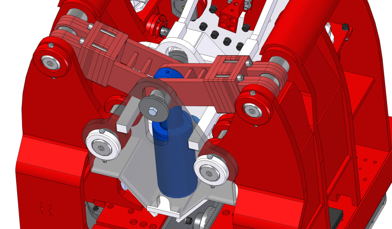
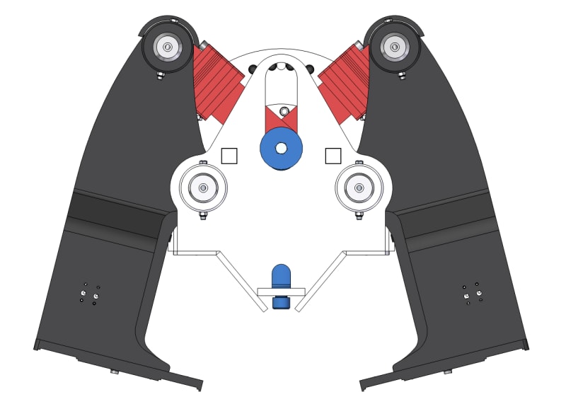
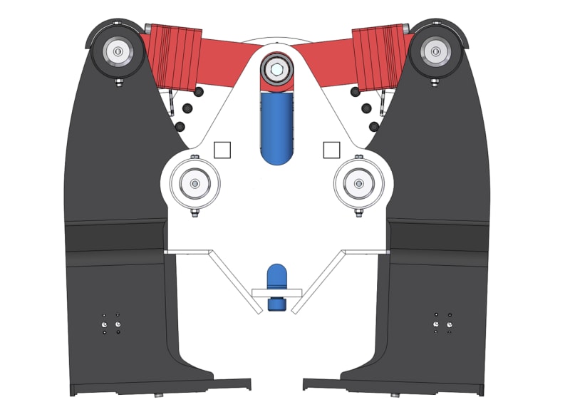
(x2) arms which hinge are driven by a hydraulic cylinder. When the cylinder is extended the arms pivot forming a clamp.
I've tested the clamp force of the cylinder on the application and recorded 64t but would like to make sense of the what's going on as we were expecting closer to 100t. There are some obvious friction point which would reduce the clamp force, but didn't expect it to be so much!
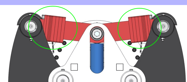
The cylinder (blue) is in the retracted position here:
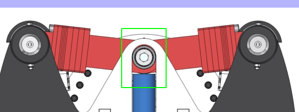
Cylinder extended shown in the image below:
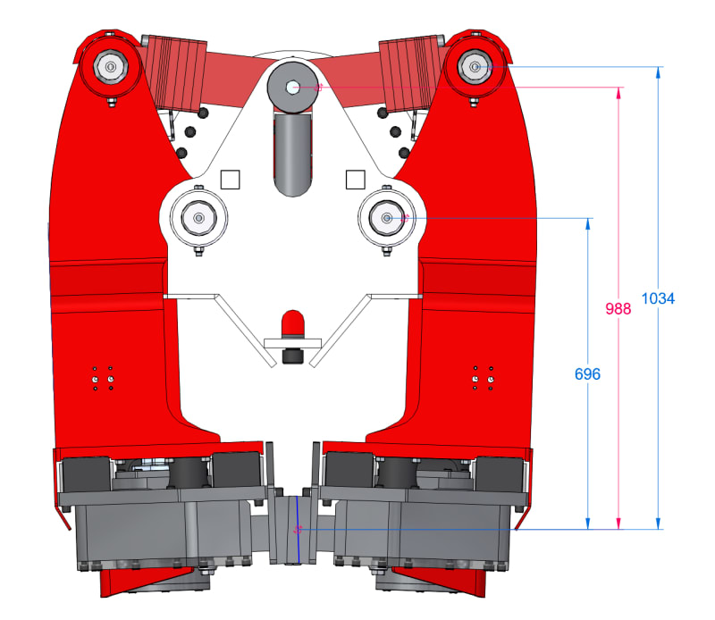
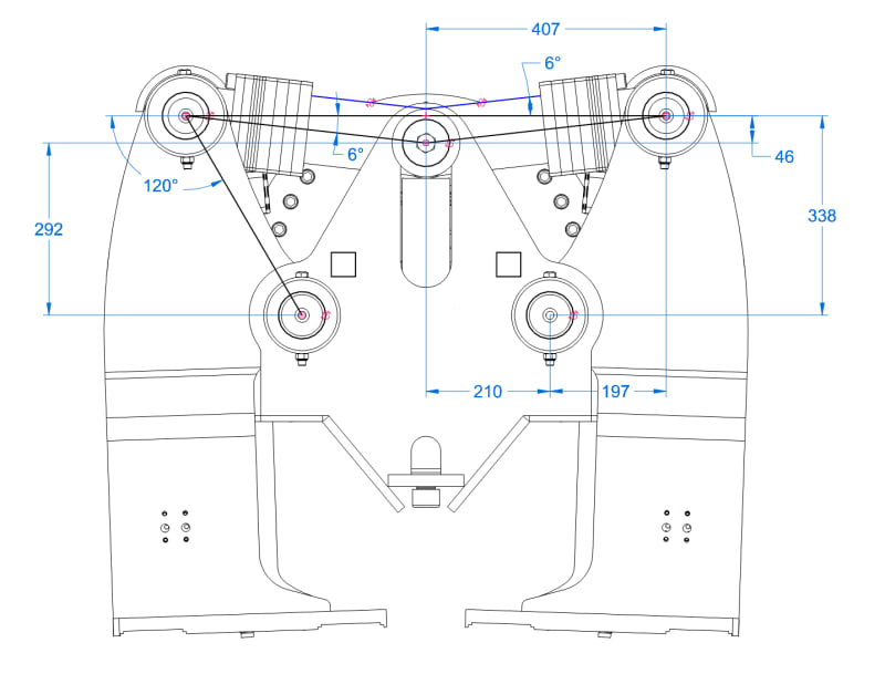
A few dimensions and angles for calculations:
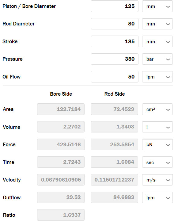
Some additional info on the cylinder (ignore flow)
Thanks in advance guys!
I'm new to this forum. Have found it very useful over the years so finally decided to join!
I have a problem to get to the bottom of and would like a hand to ensure I get the correct answer.
We have a construction application (Side-Grip) which is used to drive steel into the ground. I'm trying to establish the clamp force generated.
(x2) arms which hinge are driven by a hydraulic cylinder. When the cylinder is extended the arms pivot forming a clamp.
I've tested the clamp force of the cylinder on the application and recorded 64t but would like to make sense of the what's going on as we were expecting closer to 100t. There are some obvious friction point which would reduce the clamp force, but didn't expect it to be so much!
The cylinder (blue) is in the retracted position here:

Cylinder extended shown in the image below:

A few dimensions and angles for calculations:

Some additional info on the cylinder (ignore flow)

Thanks in advance guys!

