Continue to Site

Eng-Tips is the largest engineering community on the Internet

Intelligent Work Forums for Engineering Professionals

  • Congratulations cowski on being selected by the Eng-Tips community for having the most helpful posts in the forums last week. Way to Go!

Buried Double Wall Pipe Interaction (Bearing)

Status
Not open for further replies.

MechStruct1

Structural
Sep 8, 2010
15
Let's start with a buried double wall pipe. Let's say the carrier pipe is hot and the encasement pipe is cold. The former expands, the latter contracts. Thermal expansion loops are integrated in the system at calculated pipe span lengths to avoid interaction between inner and outer pipes (clashing) near changes in direction. Using AutoPIPE (or similar piping software), fictitious restraints (with gaps) can be added between the inner and outer pipe at coincident nodes near these changes in direction to verify that no load is getting transferred between the bends of the inner and outer pipes (and hence, no inner pipes will virtually pass through their encasement pipe).

Here is the problem: With a contracting outer pipe and an expanding inner pipe, a large number of expansion loops are needed (in areas where they will not fit, in some cases) due to the limited span length calculated based on the gaps between the pipe and the amount of thermal expansion.

So I pose the question: What if we allowed the carrier pipe to bear on the inside of the encasement pipe? Is there any guidance for this in B31 codes? I imagine that concentrated bearing loads will develop unwanted stress concentrations, but at what point of loading is this deemed an unacceptable level? Is this a bad practice? Is this left to the designer/engineer/owner to determine?
 
Replies continue below

Recommended for you

Allowing the interior pipe to bear on the inside of the exterior pipe is allowing far too much lateral displacement of the interior pipe-column, which will contribute to axial buckling failure of the interior pipe, as that will undoubtedly have a considerable compression load when hot, which will tend to put an equal and opposite tensile stress on the outer casing, which will only tend to exacerbate the buckling of the interior pipe. Alternatively you might want to think about pretensioning the interior pipe then welding each end to the outer casing, such that compressive stresses are also preloaded into the outer casing. Later the heating load of the interior pipe when operating will tend to counteract the pretensioning of the interior pipe, reducing net axial stress of the interior pipe, which will also reduce the net axial tension stress of the exterior pipe.

Technology is stealing American jobs. Stop H1-Bs for robots.
 
That's basically what people do. Somehow ( hot fluid or heating cables turned on) heat up your inner pipe with one free end and let it expand. Once it gets to temp rapidly clamp it then weld it to the outer pipe.

If you have a straight line then you only need to do this when you come to a bend.

What's in the bit between inner and outer pipe?
Is this a real system or just thinking about it?

Remember - More details = better answers
Also: If you get a response it's polite to respond to it.
 
First of all, thank you for your responses!

This is a real system that has a 3" inner pipe carrying hot water (~200deg F) and vertically supported (with supports connected to outer pipe) in a 6" outer pipe. Owner requires a low installation temperature of 60deg F for pipe stress analyses, so we're looking at a 140-degree thermal delta. Only air between inner and outer pipe.

My thought regarding the inner pipe bearing on the outer pipe is that it seems to me that stresses in the inner pipe would be relaxed (a certain amount) since the outer pipe is bearing against the soil which has some flexibility (compared to a concrete anchor). The fabricators of this system will not be allowed to hot-spring weld the pipes to each other.

It sounds like (from LittleInch) that the code is silent on this topic. Thank you for your responses.
 
not be allowed to hot-spring
Then it will also be possible that the this will be overstressed during operation, or you may buckle the inside pipe and get your bearing on the inside of the carrier pipe, whether you want it or not. Or the 3" will have a lot of lateral spacers to prevent buckling, or your 3" will have extremely thick wall.

What pipe material and wall thicknesses are you planning on using?


Technology is stealing American jobs. Stop H1-Bs for robots.
 
So in essence you have a 3" pipe on simple supports, just that your freedom of movement is limited to the bend ID. Unless your supports are really low friction the system will become restrained over long distances (150m?) and if it doesn't buckle then you could run long distances with only an end displacement based on a relatively short distance.

If you used a proper spacer / spider at suitable intervals (3m?) then you should be able to run very long distances in a straight line with support in all directions.

At the bends you might need to go to a bigger pipe size just for the bends to allow it to move axially, but is that a big problem?

Unless you're doing this as a double containment type of thing, I'm puzzled why you're going to the expense of a pipe in pipe system and not just insulate the thing??

Remember - More details = better answers
Also: If you get a response it's polite to respond to it.
 
Good thing this is only for hot water.

Technology is stealing American jobs. Stop visas for robots.
 
The inner pipe is stainless, STD wall and the outer pipe is Carbon Steel, STD wall. I believe there will be some intermediate lateral supports along the inner piping in addition to the vertical supports. But these will be allowed to "float" (with some steel-to-steel friction) on the ID of the outer pipe without being welded to the outer pipe.
 
That's not pipe bearing on pipe. That's a carrier pipe installed in the casing pipe centered with spacing rings. That's exactly what you need to do to support the carrier pipe to keep it from bending inside the casing pipe and to shorten the critical buckling length to prevent lateral buckling inside the casing pipe.

What you need to decide next will depend on how you intend this to work. I get the feeling that the carrier pipe is intended to slide inside the casing pipe. Am I to understand that the carrier pipe will not be welded to the casing pipe at any point? So it is just like a hot pipe sliding inside a cold "tunnel" pipe. How far between expansion loops? Will you pull the carrier pipe through the tunnel pipe in segments equal to the distance between expansion loops?

What diameters?

Technology is stealing American jobs. Stop visas for robots.
 
I get the feeling that the carrier pipe is intended to slide inside the casing pipe. Am I to understand that the carrier pipe will not be welded to the casing pipe at any point? So it is just like a hot pipe sliding inside a cold "tunnel" pipe. How far between expansion loops?

You are right on with your understanding of the hot guided pipe sliding inside a cold "tunnel" pipe. We need expansion loops approximately every 41 feet (according to our calculations so that the inner pipe does not bear on the outer pipe). This is for a 3" STD carrier pipe and a 6" STD encasement pipe.
 
Then why on earth do you think you need to model the outer pipe? If there is no touching of inner to outer pipe, other than friction, you have only to model the hot pipe sliding on some kind of support, wherever you have located the spacers. No need to consider the outer pipe at all. Just sure the outer pipe is large enough to accommodate the expansion of the interior pipe without allowing any touching.

Technology is stealing American jobs. Stop visas for robots.
 
140F (+-30C) is not much expansion. Let the pipe go in to compression and see what the strain/stress is. I think you find the inner pipe will be fine. Your other casing will get heated by the inner pipe. Because the outer pipe is held by the soil, you may find the higher stresses are in the outer pipe.

Geothermal wells have steel casing cemented in the ground and operate at 300C and are OK most of the time. Then again never let drillers design piping.

 
Well... you can exactly say it will be fine in this case, because here it is a small 3" pipe and the Euler buckling load depends on the length between sidesway supports that prevent lateral movement that initiates buckling, which here we don't know, not that a 3" pipe has a great axial load carrying capacity anyway. This is also far different from a pipe "cemented in the ground" as cementing would theoretically make the unbraced pipe columns laterally unsupported buckling lengths of 0, effectively prohibiting Euler buckling entirely.

"He's declaring war on the planet itself."- Vicente Fox
 
"We need expansion loops approximately every 41 feet (according to our calculations so that the inner pipe does not bear on the outer pipe). "

Care to elaborate? I get a 140F expansion on 41 ft length of pipe to be max 0.5" total. At either end you have 1.5" min before you hit the outer bend at each end so 3" in total.

If you know your issue is expansion then don't centre the inner bend in the loop so can get another 1-2" easily. I would model a very long length of straight pipe ( say 2000m) and see what happens if you fix one end and let the other end float. My guess is that the pipe will eventually stop expanding and "lock up". Then look to see how you can deal with the end expansion or at any bends.

Still not sure why you're doing this though??

Remember - More details = better answers
Also: If you get a response it's polite to respond to it.
 
MechStruct1:
My quick look finds that the coefficient of expansion and contraction for carbon steel is about .0000065, and that for stainless steel is about .0000099 ("/"/deg. F). Given 140̊F temp. delta, and 41' pipe length: carbon stl. implies about (.0000065)(140)(41' x 12) = .45" length change, or 1.09" per 100' and delta T of 140̊F; the stainless stl. implies about (.0000099)(140)(41' x 12) = .68" length change, or 1.66" per 100' and delta T of 140̊F. That expansion will obviously act differently at a tight 90̊ bend, than it will at a nice sweeping (large radius) bend. And, it will also act differently if all of the expansion can happen, at one bend from both directions. Mightn’t it be wise to fix the carrier pipe to the casing pipe at about the mid point of each long straight run, to assure that all of the expansion doesn’t happen at one bend?

Why is this pipe cased, how long is it, and what are its plan and elevation views, in terms of bends, types of bends, straight lengths, etc? Is the pipe cases for protection from the outside, or is it cased for safety against an internal, carrier pipe, failure/rupture? These questions would seem to me to enter into the design considerations. You said...., “Owner requires a low installation temperature of 60deg F for pipe stress analyses, so we're looking at a 140-degree thermal delta. Only air between inner and outer pipe.” But, obviously, the pipe stress analysis has to consider both extreme conditions.
 
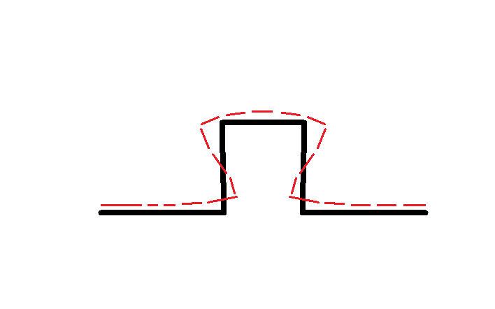
loop_expansion_lbjnju.png


There is a kickout tendency at the top of the loop which gives the bends both X and Y displacements, or if kickout is restrained, can increase friction on spacers near the bends. Could depend on how tightly the carrier pipe is held within the casing.

"He's declaring war on the planet itself."- Vicente Fox
 
Status
Not open for further replies.

Part and Inventory Search

Sponsor