Tek-Tips is the largest IT community on the Internet today!

Members share and learn making Tek-Tips Forums the best source of peer-reviewed technical information on the Internet!

  • Congratulations TugboatEng on being selected by the Eng-Tips community for having the most helpful posts in the forums last week. Way to Go!

Bolt force in sleeve connection

SALTRAM4567777

Structural
Joined
Aug 11, 2020
Messages
99
Location
AE
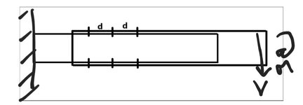
I have a cantilevered steel beam, and the supplier is placing an aluminum sleeve beam. The sleeve is connected to the cantilever via mechanical fasteners (screws). How to get the forces in screws. Refer attached figure.
 

Attachments

  • Screenshot_20250711_193324_Docs.jpg
    Screenshot_20250711_193324_Docs.jpg
    24.4 KB · Views: 30
What is the cross section of the beams? Acc. to your description, an aluminium telescopic RHS is located on the cantilever steel beam. In this case , the BM and Vertical force will be resisted by sleeve and the insert steel beam . The screws will work just to keep the sleeve in place .
 
You could look at the joint as a socket.

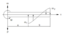
Example of a loaded socket. The inner and outer parts will experience shear and bending due to the distributed contact load. The max distributed load can be used to derive hoop stress. I suggest having a look at the subject.

1752259968348.png
 
Last edited:
Your sketch shows gaps top and bottom between the components. If the sleeve is laid on the beam with all the gap at the bottom, then the top-left fastener is in tension and the lower left is either compression or zero at the same time depending on whether it has a pilot hole or not. In any event, how much "gap" is really present and how will it be divided up?
 
Can the annular region between the steel and aluminum sleeve be grouted? (similar to a mechanical rebar splicer)

Then the screws will very clearly not be doing anything other than keeping the sleeve from sliding.
 

Part and Inventory Search

Sponsor

Back
Top