Continue to Site

Eng-Tips is the largest engineering community on the Internet

Intelligent Work Forums for Engineering Professionals

  • Congratulations waross on being selected by the Eng-Tips community for having the most helpful posts in the forums last week. Way to Go!

Best Practices - Skin Repair of Trimout Over Circumferential Splice

LiftDivergence

Aerospace
Jan 15, 2014
273
Hi all,

A few months ago I saw an post to the "Aircraft Structures" group on LinkedIn. I'm not going to link to to the post because I don't want to link to external sites in the forum. But this is a public group on LinkedIn with ~27,000 members where various aircraft structures are discussed, usually structural repairs.

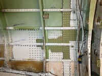
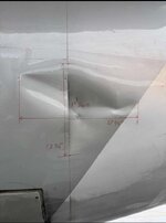
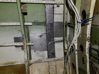
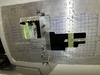
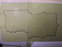
The post in question was showing a repair for an aft fuselage skin belt loader impact on a circumferential splice. A large area of the skin was pretty severely dented and buckled in. They trimmed out a large area both skin panels across the splice. I have attached some pictures of the trimout and also the completed repair (external and internal).

What immediately struck me about the repair was their choice to design it as a "split patch". Effectively, one doubler for each skin panel with no continuity between them (other than the replaced production internal splice strap).

In my experience, I would have expected a repair for this damage would either have a continuous doubler over the splice, or a tripler layer over the split doublers. This comes both from familiarity with SRM repairs for several different makes/models of aircraft where a trimout is made on a skin splice, and from analysis experience of reinforcements spanning damage across splices.

There is some discussion on the post pointing this out. However, the individual who posted the repair seemed adamant that this was correct.

I'm curious what people think of the pros & cons of this design. I have my opinion of course, but I'm curious what other peoples experiences are.
1736374979000.jpg

1736374973125.jpg

1736374980757.jpg
 
Opinions are like ...

If I had a to patch over a splice strap, I would probably (depending on specifics blah, blah, blah ...) combine the splice strap into the repair dbr ...

cut out the damage (or cancer as I'll often call it),
rebuild frames and stringers,
then add a large repair dblr over the cut-out and splice into the external splice strap (and this could be simple butt joint or a small splice strap).

To say a particular repair is "right" (which implies all others are "wrong") is IMHO pedantic ... so long as the repair considers all the necessary issues (particularly DTA) then all should be "good". Sure some repairs will be lighter than others, but is that Really significant ? Sure, it can be, but often isn't. Sure there are badly designed repairs ... because they haven't considered some aspect or another (like super heavy repair doublers, attracting load, making the "repair" worse).

We had an operator do a repair on something we'd built (many years before) under their own paperwork, so not my problem. But I looked at it and was pretty horrified ... they had rebuilt the OEM structure (that had cracked) precisely without thinking/asking and it was pretty "wimpy" ('cause that suited the OEM's environment). Making the repair match exactly the OEM structure (like splitting the repair dblr into two pieces to match the OEM skin panels) is not IMHO the right thing to do (by default).
 
Is this correct- that the original skin had a discontinuity over the middle of the internal splice strap and that the repair has the same discontinuity over the same section internal splice strap replacement?

Is it possible the patches were removed from out-of-service aircraft rather than having custom formed replacements?

A single piece would also be stiffer across the splice than the surrounding material, though I suppose the doublers already are.

It doesn't look like there's any fundamental problem with the patch.
 
I can see some "hand wringing" over the single repair patch creating a different loadpath over the skin splice, and how some may want to repeat the fuselage testing to account for this. But I'd've thought that this additional loadpath over the fuselage splice makes it more effective (and I hear "exactly, it'll attract more load than the OEM design ...") but I see the splice joint as trying to make the edges of the fuselage panels "disappear" and anything that makes this better is good (if it is fully analyzed ... "so how do you analyze for the additional load ?").

I would've made it a single repair dblr and rested very well (I would've been more worried about some unnoticed damage from the original incident ... maybe annual visual inspections of the surrounds to verify).
 
10 points to the baggage handler for missing the frames :)
 
I have less experience with metal fuselages than composite structures, but I disagree,
I would repair as shown in the photos; then the bolted joint load transfer will be very similar to baseline structure, and there will not be any stress concentrations in the doubler where it spans the splices; particularly when the doubler is not a simple rectangle but has corners at the splice.
And definitely if this is a composite fuselage, do not put a doubler spanning over a body splice location.
 
Good discussion points. I agree the concept of "right" and "wrong" is only relevant insomuch as the repair needs structural substantiation which is approved by an authorized representative, which we have to assume it was.

However, I do feel that there are objectively relatively better and worse repair practices. And my main concern is that the linkedin forum is highly active with a lot of M&Ps, etc. looking at this.

Every repair from a structural repair manual I am familiar with (Boeing, MD, Airbus, Embraer, etc) were a trimout of skin common to a splice takes place - the reinforcing material spans OVER the splice.

And not just that - from an analysis perspective, the skin and circumferential splice plate are biaxially loaded. Yes, the skin panels normally terminate at this location. But the repair is affecting the total stackup and the joint load transfer at the splice in both directions. The doublers are hardpointing the splice plate circumferentially and also adding stiffness and outer row R/P longitudinally. The splice plate is getting "hit harder" than it is in production. Effectively, you are asking it to function normally and also act as part of a new repair stackup.

I would WANT to be creating a new load path over the splice which is handled as part of the analysis. I think it's important to consider not just the skin, but how adding a new layer to the OML will affect all of the faying substructure. Which is IMO why any SRM repair addressing this type of damage has a layer bridging the splice.

But all perspectives are appreciated.
 

Part and Inventory Search

Sponsor