Tek-Tips is the largest IT community on the Internet today!

Members share and learn making Tek-Tips Forums the best source of peer-reviewed technical information on the Internet!

  • Congratulations cowski on being selected by the Eng-Tips community for having the most helpful posts in the forums last week. Way to Go!

Bend sheet plate (to known diameter)

  • Thread starter Thread starter intogtar
  • Start date Start date
I

intogtar

Guest
Hello all,

I have flat plate where I should draw holes and after holes are done I have to bend it to an arc shape with radius of 154mm. How it can be done?
I have attached an image with drawing in AutoCAD. How I can make this in 3D using CATIA?

THANK YOU!
 

Attachments

  • bend.jpg
    bend.jpg
    84.5 KB · Views: 10
The easiest way for a simple part like this is to use the Sheetmetal workbench.
 
The easiest way for a simple part like this is to use the Sheetmetal workbench.

Can you please tell what exact tools should I use to get my flat plate with holes to the round one?

Thank you!
 
Sorry, but I don't have access to CATIA right now and can't verify all the exact steps.

If you know how to use the Sheetmetal workbench, the process is fairly simple:
1. define the curved plate
2. unfold (flatten) the part, and add the holes
3. fold the part (with the holes) back to it's curved shape

If you're new to CATIA, I suggest you get some training.
 
OK Intogtar, here's the exact steps: (based on CATIA V5, R18)

1. Use the Generative Sheetmetal workbench (SMD license), and start by using the SheetMetal Parameters to define wall thickness and other material properties

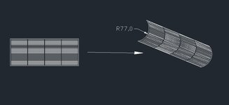
2. Create a Sketch of the side profile of the the curved plate, with bend radius and enclosed angles

3. INSERT + ROLLED WALLS + ROLLED WALL, select profile sketch, and speciafy the length of plate

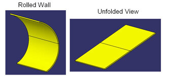
4. INSERT + VIEWS + FOLD/UNFOLD to see flat, developed shape
View attachment 818

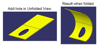
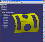
5. With unfolded (flat) shape;
5a. create a sketch of the hole
5b. INSERT + CUTTING + CUT OUT, and select sketch of the hole
5c. INSERT + VIEWS + FOLD/UNFOLD to see curved plate with deformed hole
View attachment 819

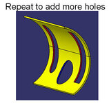
repeat for more holes
View attachment 820

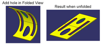
6. With folded (curved) shape;
6a. create a sketch of a another hole
6b. INSERT + CUTTING + CUT OUT, and select sketch of hole
6c. INSERT + VIEWS + FOLD/UNFOLD to see flat plate with this hole developed in flat
View attachment 821

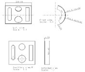
7. to make a drawing view of the developed (unfolded) plate, use the UNFOLDED VIEW tool in the Drafting workbench and add dimensions
View attachment 822
 

Attachments

  • plate1.jpg
    plate1.jpg
    27.5 KB · Views: 4
  • plate2.jpg
    plate2.jpg
    32.6 KB · Views: 2
  • plate3.jpg
    plate3.jpg
    18.5 KB · Views: 1
  • plate4.jpg
    plate4.jpg
    40.4 KB · Views: 4
  • plate5.jpg
    plate5.jpg
    60.8 KB · Views: 5
Last edited:
Notes on my last post:

1. The icons can be also be used for the all the steps. I listed the INSERT menu commands because they are easier to type in a posting like this.

2. I used CUTOUTS and sketches to define the round holes. The HOLE command can also be used.

3. I used the Generative SheetMetal workbench (not the Part Design Workbench) to build the solid model. Note the different features in the tree, and also the different set of icon commands:
View attachment 824

I tried to identify each feature with a different color, but it's difficult to see - sorry

4. This part could be done with other CATIA methods - I think this was the quickest and easiest.

5. I found out there is a limit of 5 images that can be inserted in these posts.
 

Attachments

  • plate6.jpg
    plate6.jpg
    119.9 KB · Views: 2
Last edited:

Part and Inventory Search

Sponsor

Back
Top