jaskamakkara
Structural
- May 27, 2020
- 35
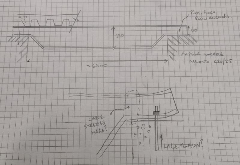
Hi, I have a need to "hang" a steel beam from two concrete beams. The top of the steel beam is 110mm above the top of the concrete but the beam needs to be at least 330mm deep so I was thinking to taper the beam ends and sit it on top of the concrete. There is a picture attached that hopefully shows it in enough detail.
My main concern is about the moment fixity. With this type of connection is it reasonable to say the beam is pin-ended? In my mind I don't think I can since there is no bolted interface or thin end-plate that will release the moments - I am concerned that the bolts at each end will end up trying to hold the beam flange down under bending and end up picking up big tensions, with the compression part of the moment couple being the interface between the flange and the concrete at the edges of the concrete beams. This lever arm will be quite small and will result in big tensions potentially. My alternative design is a bracket fixed to the concrete beam with a shear plate, this is I think better but the client doesn't like it because it's more complicated and needs much more fabrication.
It seems like such a simple connection but I can't get over this concern I have with there being some moment directed to the beam ends, the concrete is old we don't have much information on it so I am trying to keep any anchor forces to an absolute minimum.
What do you guys think? Maybe if the bottom flange of the tapered parts is thin enough then I can assume moment releases at the ends and I can ignore any nominal tensions in the bolts?
