Tek-Tips is the largest IT community on the Internet today!

Members share and learn making Tek-Tips Forums the best source of peer-reviewed technical information on the Internet!

  • Congratulations cowski on being selected by the Eng-Tips community for having the most helpful posts in the forums last week. Way to Go!

Beam Reinforcement Calculation

Nick6781

Structural
Joined
May 15, 2024
Messages
52
Location
CA
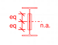
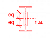
Let's say I need to use a web plate instead of a flange cover plate (I know...) to reinforce a beam. How do I calculate the required weld to ensure the section acts compositely? The shear flow equation gives the shear along a horizontal plane, but in this case, the faying surface is vertical. I can't quite wrap my head around it.


1751068113227.png
 

Attachments

  • 1751068099044.png
    1751068099044.png
    12.3 KB · Views: 2
CANPRO argues my point in that thread. The Ix of the combined section is simply the sum of the I of the beam and plates. If there was actual shear flow, the Ix of the composite section would be greater than the sum of the individual Ix's.
Thanks for sharing that thread. Appreciate @CANPRO going all in for that discussion.

Who knew shear flow was such a hotly contested subject here on eng-tips.
 
Well, it can be a bit more complicated than you might think. I would tend to agree that there is no shear flow for the OP's shape (or for the one in the referenced thread) provided the side plates or channels are carried to the supports. But usually, when side plates are added to reinforce a beam, they are not extended over the full span, so it helps to understand the shear flow formula. Each side plate puts a reaction on the beam which is very small for side plates, but not so small for side channels or other more substantial welded reinforcements.

Another complication with shear flow occurs when we design beams stressed beyond the elastic range. The factored moment M = phi*Z*Fy (Z is the plastic modulus). That may render the formula VQ/I inaccurate for part of the beam because 'I' is an elastic property.

Within the elastic range, using the shear flow formula appears to be conservative.
 
Well, it can be a bit more complicated than you might think. I would tend to agree that there is no shear flow for the OP's shape (or for the one in the referenced thread) provided the side plates or channels are carried to the supports. But usually, when side plates are added to reinforce a beam, they are not extended over the full span, so it helps to understand the shear flow formula. Each side plate puts a reaction on the beam which is very small for side plates, but not so small for side channels or other more substantial welded reinforcements.
But while it remains a symmetric member about the neutral axis there still is no longitudinal shear flow, even for "side channels or other more substantial welded reinforcements".

Another complication with shear flow occurs when we design beams stressed beyond the elastic range. The factored moment M = phi*Z*Fy (Z is the plastic modulus). That may render the formula VQ/I inaccurate for part of the beam because 'I' is an elastic property.
I disagree. 'I' is not an "elastic property" it is a geometric property. And unless the geometry of the section changes then 'I' won't change (Any plastic deformation isn't going to change the geometry significantly). Thus VQ/I doesn't become inaccurate in the plastic range.

Within the elastic range, using the shear flow formula appears to be conservative.
I'm not sure what you mean here. The shear flow formula for this example calculates out to ZERO as Q = 0.

The formula is neither conservative nor unconservative it is an exact formula from mathematical analysis.

Circling back to this:
Yes, there is. VQ/I is the shear flow for the existing beam plus two new plates where Q is taken at top (or bottom) of added plates.

If w is web thickness and t is the added plate thickness, then each weld must resist VQ/I * t/(w+2t).

It turns out that Q is unchanged by the addition of two plates, but Icomp = Ibeam + 2tddd/12 where d is plate depth.
Q is not unchanged, it is zero. As you measure the center of area of the plate to the centroid of the beam. This gives a value of 0.
 
Last edited:
I am sorry but i disagree with this comment. If the beam loaded say UDL , and if the shear force is not zero, there will be horizontal shear flow.Staggered fillet welding could be OK but it is necessary to dictate combined behavior of the section.
Why do you assert this when it goes against the theory and shear flow formula and the previously explained points?

I am sorry but i disagree with this comment. If the beam loaded say UDL , and if the shear force is not zero, there will be horizontal shear flow.Staggered fillet welding could be OK but it is necessary to dictate combined behavior of the section.
The section will behave in a combined manner purely on vertical shear transfer. Provide staggered bolts with horizontal slots and you'll have 'combined behaviour'. Both beams will deflect in unison and the added plates will provide resistance to bending.
 
But while it remains a symmetric member about the neutral axis there still is no longitudinal shear flow, even for "side channels or other more substantial welded reinforcements".
You are wrong. There is shear flow for every beam, even a simple rectangular beam.
I disagree. 'I' is not an "elastic property" it is a geometric property. And unless the geometry of the section changes then 'I' won't change (Any plastic deformation isn't going to change the geometry significantly). Thus VQ/I doesn't become inaccurate in the plastic range.
Again, you are bloody wrong! It is a geometric property which is used in the elastic range, not the plastic range.
I'm not sure what you mean here. The shear flow formula for this example calculates out to ZERO as Q = 0.

Q is not 0 for a beam with side plates. In fact, it is not 0 for any beam.

The formula is neither conservative nor unconservative it is an exact formula from mathematical analysis.
It is exact within the elastic range. It is not exact in the plastic range.
Circling back to this:

Q is not unchanged, it is zero. As you measure the center of area of the plate to the centroid of the beam. This gives a value of 0.
Q is not zero at the neutral axis, it is not zero where the web meets the flange, and it is not zero anywhere in between. I suggest you read a strength of materials textbook for the definition of Q..
 
You are wrong. There is shear flow for every beam, even a simple rectangular beam.
Well that is stating the obvious. Since we are being pedantic I should have said there is not longitudinal shear flow BETWEEN the members. In this case the beam and the plates.

Again, you are bloody wrong! It is a geometric property which is used in the elastic range, not the plastic range.
It is a geometric property (have a look at any basic definition) that exists inside the elastic range and in the plastic range. It isn't a property that disappears if there is plastic deformation. If you are referring to the EI formula to determine stiffness it is the E that effectively changes. The 'I' remains the same as long as the section retains its geometric shape.

Q is not 0 for a beam with side plates. In fact, it is not 0 for any beam.
Again I'll refer to the first line from wikipedia. "The first moment of area is based on the mathematical construct moments in metric spaces. It is a measure of the spatial distribution of a shape in relation to an axis."

In this case the axis is neutral axis. Perform calculation for the entire plate relative the the system and due to symmetry there is no longitudinal shear flow BETWEEN the plate and the web.

It is exact within the elastic range. It is not exact in the plastic range.
You keep asserting this without any explanation.
 
Well that is stating the obvious. Since we are being pedantic I should have said there is not longitudinal shear flow BETWEEN the members. In this case the beam and the plates.
Yes there is.
It is a geometric property (have a look at any basic definition) that exists inside the elastic range and in the plastic range. It isn't a property that disappears if there is plastic deformation. If you are referring to the EI formula to determine stiffness it is the E that effectively changes. The 'I' remains the same as long as the section retains its geometric shape.
My/I is not correct for stress in the plastic range.
Again I'll refer to the first line from wikipedia. "The first moment of area is based on the mathematical construct moments in metric spaces. It is a measure of the spatial distribution of a shape in relation to an axis."

In this case the axis is neutral axis. Perform calculation for the entire plate relative the the system and due to symmetry there is no longitudinal shear flow BETWEEN the plate and
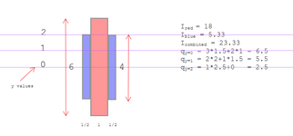
Here are a few 'q' values for your amusement. Note that q at y=2 is unchanged by the presence of side plates.
1751411195719.png


the web.


You keep asserting this without any explanation.
The explanation is that moment of inertia is the wrong property to use in the plastic or partial plastic range.
 
Last edited:
For those who like to see visuals and let computers do the work. Here is my representation of a beam with plates under UDL. I have an I-beam and two symmetrical plates with a rigid fastener staggered along the beam.


1751410897992.png

1751411179925.png

BELOW WE HAVE THE SHEAR FOR DIAGRAM SHOWING NO LONGITUDINAL SHEAR TRANSFER BETWEEN THE BEAM AND THE PLATES.

1751411304494.png

AND BELOW IS WHAT HAPPENS WHEN I OFFSET THE PLATES IN THE VERTICAL DERIECTION WE GET LONGITUDINAL SHEAR TRANSFER AS EXPECTED. INCREASING TOWARDS THE ENDS AS EXPECTED.

1751411474511.png
 
I'm not sure how that relates to this thread, but I will think about it.
 
I'm not sure how that relates to this thread, but I will think about it.
It relates because it shows the shear flow between the plates and the beam which is exactly the original question. It shows no longitudinal shear flow. In the second image I offset the plates to check that the model behaves as theory would expect, which it does.

Of course in all this discussion there longitudinal shear flow within the beam and the plates. But we don't care about that we only care about the shear flow BETWEEN the plates and the beam.
 
Shear flow BETWEEN plates and beam is not defined. The plates are welded to the web of the beam. We need to think of the red and blue plates on my sketch as a composite unit. We care about the strength of weld required to generate the shear flow in the blue plates (which is not zero).

I do not understand your recent presentation at all, but perhaps my poor old brain needs a rest.
 
We care about the strength of weld required to generate the shear flow in the blue plates (which is not zero).
The strength of the connection, weld or otherwise, required to transfer shear force longitudinal to the beam is ZERO as described by myself and others and demonstrated mathematically and via computational analysis software. Naturally you also need to transfer the vertical shear which is simply the proportion of the load on the beam relative to the stiffnesses.

Here are a few 'q' values for your amusement. Note that q at y=2 is unchanged by the presence of side plate
I didn't respond to this point earlier as I didn't know what or how your were calculating things. And I still don't. But it seems you have a non zero value for when y=0 which presumably is the at the centroid. But this flies in the face of the one of the definition of the centroid as the location where the first moment of are are equal to zero.


And I'm reposting this from the thread from 2020 just for my own benefit, to demonstrate to myself I'm not insane.
@CANPRO "if the centroids align then your Q value in your shear flow calculation goes to zero (Q=a*d, d=0)."
 
Last edited:
But d does not equal 0. Look at my diagram. Q at 0 (neutral axis) = 3*1.5 + 2*1 = 6.5
where 3 is the red area above the neutral axis and 1.5 is the distance from its centroid to the N.A.
and 2 is the area of the two blue plates above the N.A. and 1 is the distance from the centroid to the N.A.

If the dimensions are given in cm, then Q = 6.5 cm^3.

Or consider a rectangular beam, width b, depth d. Q at N.A. = b*d/2 * d/4 = bdd/8
and I = bddd/12, so VQ/Ib = V*bdd/8 * 12/bbddd = 3/2 * V/bd, a value which we know to be correct.
Check your Strength of Materials book.

Good night, I'm going to bed.
 
Last edited:
BA for reasons known only to yourself your are choosing to ignore half of the beam. The vector below the neutral axis is negative and thus the integral sum is zero. You seem to be using a different definition of Q
.1751429391851.png
https://en.wikipedia.org/wiki/First_moment_of_area

(It seems like you are attempting to calculate the shear flow due to half the composite beam at the web, this isn't the answer we are looking for. The answer we are looking for is the shear flow between the plates and the web.)

It has been linked several times now, but it doesn't seem like you've reread the previous thread despite the fact that you participated in it. The discussion covers similar topics in significant depth.
 
Last edited:
BA for reasons known only to yourself your are choosing to ignore half of the beam. The vector below the neutral axis is negative and thus the integral sum is zero. You seem to be using a different definition of Q
.View attachment 14737
https://en.wikipedia.org/wiki/First_moment_of_area
When you want to find horizontal shear, the formula which you have quoted is correct, but dA refers to the area above the level you are examining, not the total area.
https://en.wikipedia.org/wiki/First_moment_of_area
It has been linked several times now, but it doesn't seem like you've reread the previous thread despite the fact that you participated in it. The discussion covers similar topics in significant depth.
If you are talking about the link to the 2020 thread, I don't think I participated in it at the time. I have scanned it briefly in the last couple of days, but I have not had time to read it carefully. It is pretty long winded.

What I do know is that dA refers to the area above the level in question, not the whole cross section, so if Q is required at the neutral axis, dA is the area above (or below) the N.A. In no case can the value of Q be zero if it is taken anywhere between the top and bottom of the section. A beam has many different values for Q, depending on where you are trying to find the value of the horizontal shear.

Please do us all a favor and review your textbook on Strength of Materials.
.
 
A sincere thanks to continue to engage BAretired. While I continue to disagree, I appreciate a healthy discussion.

But dA refers to the area above the level you are examining, not the total area.
Where is above? Where in that formula does it say above? In the wiki page you now linked back at me it even says:
"equals the sum over all the infinitesimal parts of the shape of the area of that part times its distance from the axis [Σad]."

Likewise if you accept that the first moment of area is ZERO at the centroid then the above answer should make itself clear. If you don't accept that then please have a look at the definition of the centroid.

What I do know is that dA refers to the area above the level in question, not the whole cross section, so if Q is required at the neutral axis, dA is the area above (or below) the N.A.
When calculating the fixings required for the plate the Q in the formula VQ/I is the concerns the area of the entire plate, to which the second moment is zero. (To clarify I'm talking above the forces along the axis of the beam here, clearly some fixings are needed to transfer the shear in the direction of the load.)

In no case can the value of Q be zero if it is taken anywhere between the top and bottom of the section..
Well the first moment of area is ZERO at the centroid which is the definition of the centroid. But since we can't agree on this fact then I think we'll struggle to find common ground.
 
Last edited:

Part and Inventory Search

Sponsor

Back
Top