Doug.......certainly "A" for effort........though your analysis is off
First.......lets clarify that configuration being analyzed is for upper beam (length L/2) centered within span of lower beam (length L).....and for uniform load on upper beam only.
For more general condition length of upper beam could be different (within limits so as not to result in drastically different configuration that would not be applicable) and loading on upper beam could be whatever you want.
Taking your conclusions in order;
(1) At end of upper beam......clearly, at lowest theoretical limit of stiffness for upper beam (I-upper = 0)......and with I-lower > 0.......upper beam is in full contact along entire length of upper beam. For positive, but very low value for I-upper, some gap eventually develops. However, without at least some mathematical basis, there is no basis for claim that contact at end of I-upper is limited to point contact. In fact, for uniform load on upper beam ...and for relative stiffness used for your analysis (I-upper = (1/10) I-lower) there must be some length of contact at each end of upper beam, as discussed below.
(2) For specific case you are considering, there is contact at midspan.........but this is not always the case, as discussed below, and as discussed at length in previous posts.
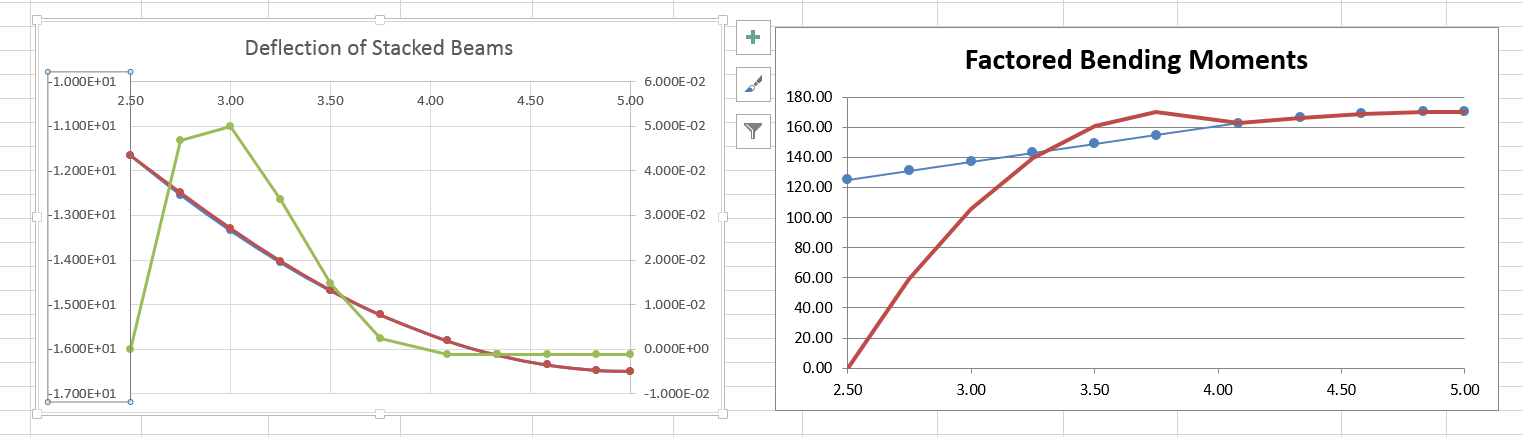
(3) This appears to be key flaw in your analysis. Moment (and shear) in each beam is not proportional to relative I-values (stiffness is not correct term since stiffness is function of E, I and L) wherever curvature is the same; see below for explanation. However, your moment graph already proves that this is not the case...........since, where red line crosses blue line, graph shows equal moments at point where the beams are not in contact and therefore do not have same curvature.
(4) Zero moment at end of upper beam is not caused (as implied by your statement) by separation of two beams somewhere between end and midspan of upper beam. Moment at end of upper beam is zero since that is always the case at end of beam that is free to rotate. Your description of moment in lower beam is correct only for x = L/4 (at end of upper beam). However, there is no obvious meaning to such statement.
(5) Meaning of "At this point" is not clear. More important is lack of free-body diagram to demonstrate "equilibrium" of upper beam.........which is most important flaw in your analysis.
Since your deflection graph lists absolute values.........you must be using specific moment of inertia values for each beam (which is fine for spreadsheet routine)........however such limited analysis is of course not useful for understanding general behavior for this setup.
Sounds like your analysis is for I-lower = 10 I-upper.........which is same as I-upper = (1/10) I-lower.
Red line in moment graphs must be for upper beam (with M = 0 at left end).
Explanation that solution is "very sensitive to starting value" is strong indicator that your analysis is not quite correct.
Based on your "timeline" of events, it sounds like you have started from an incorrect assumption that both beams start off with contact at midspan (only?)........and that the ends of upper beam mysteriously rise up above lower beam and then "reconnect" just as mysteriously at some future (unspecified) time.
If, as should be the case, analysis is for any moment of inertia values for upper beam (I-upper) and lower beam (I-lower)........then your claim that there must be contact at midspan of lower beam is not correct unless I-lower is infinite (in which case it is bedrock, not a beam!) or, more usefully, large enough.......relative to upper beam........such that deflection of upper beam results in such contact. Obviously, for a wide range of I-upper values (starting of course with theoretical "infinite"), deflection of upper beam (acting as simply-supported beam spanning between ends which are in contact with lower beam) is not enough to result in contact at midspan of each beam (for stated configuration).
For real-life demonstration of this behavior.......just review photos provided by SRE (above) which clearly show ......for point load and uniform load on upper beam.......continuous gap between both beams except at ends of upper beam.
As reported in previous posts........it is relatively straightforward to calculate value of I-upper that results in contact at midspan.........which is I-upper = (2/11) I-lower.
However, with I-upper = (2/11) I-lower, there is not yet any redistribution of load (compared to contact only at ends of upper beam) since upper beam has barely made contact (picture upper beam one micron above lower beam for I-upper infinitesimally less than (2/11) I-upper).
As value of I-upper is reduced below "first contact" limit (FCL; (2/11)I-lower ].......redistribution of load onto lower beam occurs, with lower beam providing an effective spring-type support for upper beam at midspan (of both beams). However, as discussed in my previous post, this is when behavior gets complex since contact at ends and midspan of upper beam is now over some length (instead of just point)......although, for at least some I-upper values near FCL, an assumption of point contact remains accurate enough for engineering purposes certainly and very likely for pure-analysis purposes as well.
As for relative slopes
at end of upper beam (again, for stated case);
Slope of I-upper = wL^3/[192 E I-upper].........with "L" of course defined as L-lower.........and L-upper = L-lower /2 or L/2
Slope of I-lower = wL^3/[64 E I-lower].........obtained most conveniently via conjugate beam
Equating these two expressions results in.........I-upper = I-lower / 3
So that...........when I-upper is 33.3% of I-lower........slope (curvature) of each beam is equal at end of upper beam
Since this value of I-upper is greater than (as previously reported) value of I-upper that would result in first contact at midspan [ I-upper = (2/11) I-lower] if there were only point contact at each end......it is reasonable to conclude that slope of each beam is then the same at end of upper beam, before there is any contact at midspan.
As I-upper is reduced below (I-lower / 3)....but is greater than (2/11) I-lower (meaning no contact at midspan).......one of the following must be the condition at end of upper beam;
(1) Length of contact at each end must then be greater than zero
or
(2) Point of contact occurs inboard of end of upper beam........and there is no contact (gap) outboard of this new point of contact
For I-upper just less than I-lower / 3......slope of upper beam (at end) would have to be greater than slope of lower beam, except for the "obstruction" caused by contact with lower beam. The lower beam effectively causes an opposite rotation for end of upper beam............which is effectively the same as would occur if a moment is applied at end of upper beam causing opposite rotation. By calculating the difference in rotation for upper beam (that is, the "lost" rotation compared to condition without such obstruction), we can calculate amount of effective moment that has been applied by the upward force from lower beam.
Having now a modified expression for rotation of upper beam. If we know where to apply this moment (in opposite sense) to lower beam, we can then also determine modified expression for rotation of lower beam........which is necessary since force applied by upper beam is now distributed instead of point. We may then calculate modified slope of each beam along length of lower beam (which is of course the baseline).
Problem of course is determining where along lower beam this effective moment occurs (for lower beam)........or, stating another way, shape of distributed force along length of contact ...constant uniform, or uniformly varying or non-linear?
For relatively small length of contact......we might "reasonably" assume constant uniform distribution. However, as length of contact increases, shape of this distribution becomes critical for accurate analysis.
More development of necessary expressions is required for complete analytical solution........and makes me wonder whether anyone has bothered to do this before! (very likely yes, somewhere, sometime)
However, basic behavior is not as proposed by Doug above.
Finally.....claim that moment in each beam is proportional to relative I-values ......when beams have same slope (curvature)......is not correct. Moment graph by Doug shows that is not correct as previously noted. However, for more analytical demonstration........we can start by calculating moment in each beam at midspan, since (for this case) slope of each beam is of course the same value; zero.
M-upper = w(L/2)^2/8 = wL^2/32
M-lower = (wL/4)(L/2) - (wL/4)(L/4) = wL^2/8 - wL^2/16 = wL^2/16
So M-lower = 2 M-upper..........for all I-values for each beam...........that is, moment in each beam is not dependent on relative I-values
Also.......when slope at end of upper beam first equals slope of lower beam........moments are clearly not equal since M-upper = 0 and M-lower = (wL/4) (L/4) = wL^2/16
John F Mann, PE