HanStrulo: I think you might be mixing up a bit of terminology. So lets take a step back to ask ourselves what exactly these class identification criteria are used for. They are intended to address issues relating to how member capacity can be limited by local buckling (rather than global buckling) in certain circumstances. Unfortunately the presence of local bucking means we need to check to see if it governs the design, which would otherwise be a lot of work. However, by assigning a cap to the global capacity based on slenderness, these local buckling checks are implicitly already done for us! The criteria essentially make it so that we, as designers, don't have to worry about local buckling checks or knowing when they will govern our designs.
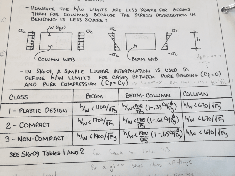
As you no doubt know, buckling is a phenomenon that only appears in compression members. So when you speak of class identification it is not of compression versus bending, rather it is of pure axial compression versus flexure induced compression (Tables 1 and 2 respectively).
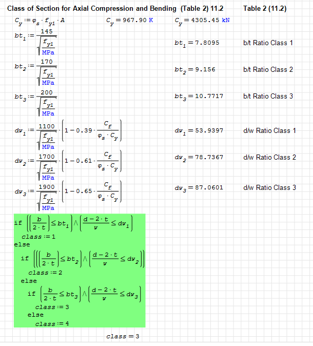
If you take a look at Table 1 from S16 above you'll see that axially loaded compression members don't even really have classes. They have absolute limits. And unless you fancy an adventure, you always just stay under the limits. So really there is no such thing as "class 2 for axial" as you can see. There is only under the limits or not for pure axial compression!
If you look at Table 2 you'll see there are ranges and classes for various ratios for flange and web dimensions for members in flexure. For W-sections the flange limit / class is irrespective of axial loading. Nothing to do with it! As far as a flange check is concerned a beam is a beam is a beam. The web check is another matter. You'll note the presence of axial load modifiers contained within the web class check
(1 - 0.39Cf/Phi*Cy) and these are constructed such that they are interpolated between full flexure and full axial.
Here is what I mean:
Axial Only Members
h/t <= 670 / sqrt(Fy)
Flexure Only Members (class 1)
h/w <= 1100 / sqrt(Fy)
Combined Flexure and Axial (class 1)
h/w <= 1100 / sqrt(Fy) * (1 - 0.39Cf/Phi*Cy)
Lets investigate that combined check. What happens if the factored compression force, Cf, is at max capacity for the member?
(1 - 0.39Cf/Phi*Cy) clearly equals 0.61 which if we put back into the combined equation we get
h/w <= 1100 / sqrt(Fy) * 0.61 =
671 / sqrt (Fy)
That's the exact same as the Axial only member (after rounding)!
What if the compression force is 0? Well the multiplier equals just 1 and we get
h/w <= 1100 / sqrt(Fy) * (1 - 0) =
1100 / sqrt(Fy)
The criteria for flexure only!
That's what I mean by linear interpolation between full axial and full flexure. It's already taken into account in that equation set for webs in Table 2.
Mixed flanges and web classes
As dik noted, the most slender class governs the design for everything. So if a web is class 1 but the flange is class 2, your member is class 2 for all design purposes. This has to be the way or local buckling will occur before you reach your design capacity.
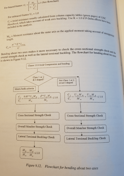
Beam Columns
The only checks you need to do for beam columns (for local buckling purposes) is the flange check in Table 2 and the web check in table 2. No different than for pure flexure members. Of course, as noted the more slender class governs the design. Hopefully it is clear now that there is no separate check for class of a beam column member considering only axial compression. It is inherent in this check from Table 2!
In the above example (class 1 web, class 2 flange, meets requirements of Table 1 for axial compressive members) we would say this member is class 2. Full-stop!
dik: Not cut-off per se but it does continue to discuss what happens when bending occurs in both axis directions
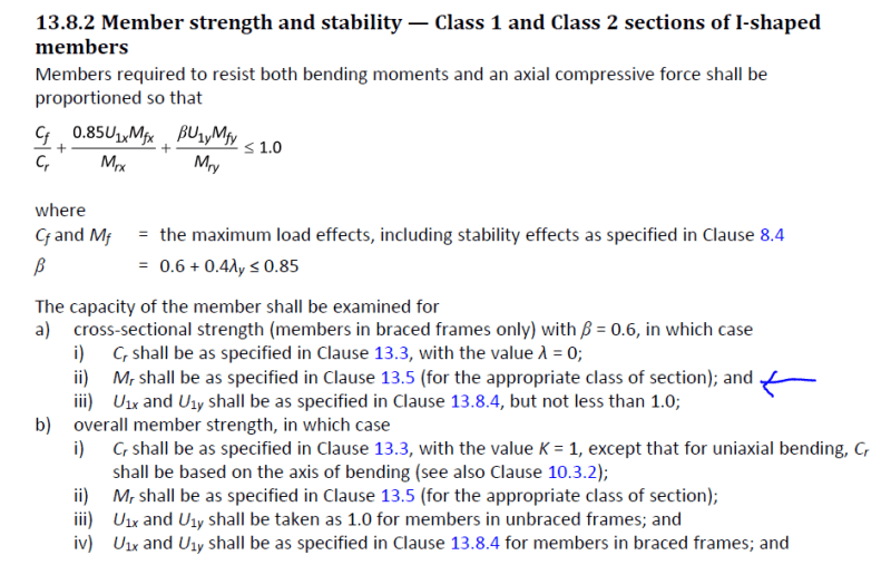
jayrod: You are correct. Moment capacity is determined by pure flexure equations up in sec 13.5 like the following


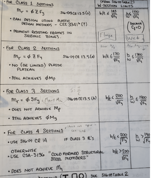
![[lol]](/data/assets/smilies/lol.gif "[lol] [lol]") ... A class other than 1 or 2 may fail locally by buckling before Mr is reached. Just added... even if I don't need stiffeners in beams continuous over columns, I still add them... in the event of an overload, they help maintain the stability of the cross-section.
... A class other than 1 or 2 may fail locally by buckling before Mr is reached. Just added... even if I don't need stiffeners in beams continuous over columns, I still add them... in the event of an overload, they help maintain the stability of the cross-section.