Navigation
Install the app
How to install the app on iOS
Follow along with the video below to see how to install our site as a web app on your home screen.
Note: This feature may not be available in some browsers.
More options
Style variation
-
Congratulations JAE on being selected by the Eng-Tips community for having the most helpful posts in the forums last week. Way to Go!
You are using an out of date browser. It may not display this or other websites correctly.
You should upgrade or use an alternative browser.
You should upgrade or use an alternative browser.
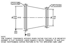
AVG and F symbol - fig 8-14/2018
- Thread starter greenimi
- Start date
Burunduk
Mechanical
- May 2, 2019
- 2,551
but why they are doing a half-assed job?
The answer for you is the one you like better:
a) They do a half-assed job because they don't get paid for it.
b) Well, at least they don't get paid for that lousy job. Thank God!
mfgenggear
Aerospace
so I had this wrong the note on the fiquire contradicts the free state symbol.As all ways I am scratching my head.
But my assumption is hollow or tube like parts are
Flimsy. And even thou are in size. Have to be
In the restrained condition. In the old days
A note was applied (inspected in the restrained condition) in the example above a fixture is required, mounted on A & B.
Thus intent it will assemble, runout acceptable.
Is this a correct assumption?
I ask AI because it is smarter than I am
Overview

In ASME GD&T, a circle enclosing the letter "F" signifies a "Free State" tolerance. This indicates that the feature's geometric tolerance is assessed in an unrestrained condition, without any applied force or load.
Elaboration:
- The Free State symbol (F in a circle) is used in conjunction with a feature control frame to indicate that the geometric tolerance applies when the feature is not constrained or loaded.
- This means the tolerance applies regardless of whether the part is deformed by external forces or by the way it's supported during manufacturing or assembly.
- For example, if a hole is specified with a free state tolerance for perpendicularity, the tolerance would apply even if the hole deforms slightly due to a clamping force.
Burunduk
Mechanical
- May 2, 2019
- 2,551
"
- For example, if a hole is specified with a free state tolerance for perpendicularity, the tolerance would apply even if the hole deforms slightly due to a clamping force. "
mfgenggear
Aerospace
Burunduk"
This is wrong. If the tolerance is applied at free state, there must be no clamping forces or elastic deformation when the part is positioned for inspection. Be careful with AI.
- For example, if a hole is specified with a free state tolerance for perpendicularity, the tolerance would apply even if the hole deforms slightly due to a clamping force. "
I defer to you and accept your correction.
As the ASME Handbook gets more complicated.
Definitely we need to all calaborate. And brain storm these issues. I commend greenimi on this one. I guess this one really depends on what an engineer needs and the correct GD&T.
In my line of work hollow or solid shaft are inspected between centers. In some cases some type of arbor is used to restrain parts inside datums per drawing or as tooling.
Many form tolerances are used often.
Runout, perpendicular, parallel, total runout , roundness and cylindricity . And more.
Inspection in free state generally mentions
That part must be inspected with out restrained.
And restrained condition use to mean it can be fixtures in some manner. To me it's that simple.
With out physical actual training this us complex to train verbally or written. And takes years of experience.
I have agree with Dave. ASME is making it to complex and is stirring the pot , so to say.
Burunduk
Mechanical
- May 2, 2019
- 2,551
mfgenggear,
At free state you may still need to support or hold the part in some manner, by devices used as datum simulators, but not only.
Datum simulators could be a granite slab, angle block, v-block, centers, etc. However, you don't clamp to them by force at free state. If the part deformed when you fixtured it for inspection, that is not a free state measurement. Free state is the default and as such it does not normally need any indication on the drawing, except for those cases in which a restrained condition is required by a drawing note. A restraint note such as shown at the bottom of the figure in OP's post overrides the free state default. But unlike that specific figure, often it applies UNLESS OTHERWISE SPECIFIED. Then the otherwise specified controls or datum references are the ones indicated by the free state symbol (circled F).
Last edited:
mfgenggear
Aerospace
Yes I agree, but technically it's not restraing it's locating. But I am cutting hairs.mfgenggear,
At free state you may still need to support or hold the part in some manner, by devices used as datum simulators, but not only.
Datum simulators could be a granite slab, angle block, v-block, centers, etc. However, you don't clamp to them by force at free state. If the part deformed when you fixtured it for inspection, that is not a free state measurement. Free state is the default and as such it does not normally need any indication on the drawing, except for those cases in which a restrained condition is required by a drawing note. A restraint note such as shown at the bottom of the figure in OP's post overrides the free state default. But unlike that specific figure, often it applies UNLESS OTHERWISE SPECIFIED. Then the otherwise specified controls or datum references are the ones indicated by the free state symbol (circled F).
It's all good. The challenging parts are ring gears.
Keeping them round. In the unrestrained condition.
Sitting on a granite surface plate verifying flatness and roundness. I guess it what we think we are doing in our head.
Similar threads
- Replies
- 62
- Views
- 10K
- Locked
- Question
- Replies
- 1
- Views
- 311
- Locked
- Question
- Replies
- 9
- Views
- 5K
- Locked
- Question
- Replies
- 5
- Views
- 3K
- Locked
- Question
- Replies
- 6
- Views
- 620

