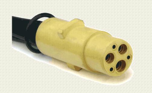
What Itsmoked showed was a female cord connector with pilot poles that are used with an equipment ground check relay at the receptacle controller that will only energize the receptacle if the equipment grounding pathway including the appliance frame is complete. This is required by US federal law for both commercial shore-to-ship power cords and mining applications as well as NEC 250.188 for medium voltage cords for mobile and portable machinery. Walther Electric and some other compoanies make these kinds of receptacles, plugs, and so forth for 60 to 400 amps for 12o volts to 690 volts. ( That is not a typo. MEG makes 60 Hertz 690-volt water cooled motors.
and Telemechanique make 690-volt VFDs. ) The rest of this is to some extent explanatory as to why this stuff is used
What NEC Article 555 requires for commercial shore-to-ship power is TOTALLY ILLEGAL in the eyes of US Bureau of Shipping. Since federal law trumps NEC NEC 555 does not apply to commercial shore power cords. You are not allowed by federal law to power a commercial rowboat off of a GFCI receptacle if that is the only electric shock protection. There must be a receptacle controller between the GFCI and the receptacle that will only energize the receptacle if the downstream equipment ground is complete.
For 120 to 600 volt applications that are under 60 amperes smcelectrical.com makes pilot wireless ground check relays that send an audio tone over the current carrying wires, through an audio network in the appliance, through the appliance frame, and back through the equipment ground. This also requires an isolated ground receptacle but with such marking removed or a conventional receptacle mounted on an insulating plate or insulating box.
If you go over to
and enter in ground check relay + shore power you will find that one of the mining electrical equipment manufacturers built a 6,00-volt plus 11,000-volt shore power system in Alaska for one of the cruise ship lines. A typical cruise ship uses 11 to 13 megawatts when docked and unoccupied and uses around 4 shore power cords. You have to remember that a shipyard or mine or steel mill are the kind of places where a 200 HP motor is a small motor and a 20 HP motor is a toy.
All of this is based on work that the United Kingdom National Coal Board did on ultrasafe power systems in the late 1950s and early 1960s. From 1963 to 1980 British coal mines had ZERO electrocution deaths as opposed to 1 or 2 deaths a year before they started rewiring their mines. Since they had 1,100-volt and 3,300-volt extension cords back then so they have been doing something right. In 1973 Congress mandated that the US mining industry switch to the British method of wiring a mine. The upper voltage limit on this technology is 24,000 volts resistance grounded.
Yes, there really is a 200-amp or 400-amp 13,800-volt receptacle that you can install 4 feet from the edge of a swimming pool, plug in a cord, run the cord across the bottom of the swimming pool, plug the other end into a substation on the other side, energize the cord, and then go swimming with perfect electrical safety. That is how difficult the electrical hazard situation is in a commercial shipyard or an mine.
What US Bureau fo Shipping requires for commercial shore power is a follows:
1. You need at least 4 ground check relays per ship.
2. At 2 power cords per ship and each one has to be qualified to act as a redundant equipment ground for all the other cords even if you only intend to put load on 1 cord.
3. All the ground check relays have to agree with each other for any of the power cords to be energized.
4. Each ground check relay ( 4 or more cords ) or pair of relays ( 2 or 3 ) have to be able to tell the difference between the equipment ground that each relay or pair of relays ( for the same cord ), the deliberate redundant grounds in the other cords, and the false pathway through the water. One way to accomplish this is to use audio tone or line frequency ground check relays each on a different frequency and then wind on an inductance core an equal number of turns of the 3 phase conductors, the equipment ground, and the 1 or 2 ground check relays.
5. 120/240 volt single phase and 4-wire 3 phase up to about 144Y249 volts can be solidly grounded or resistance grounded. Above that resistance grounding is required. This is a straight plaigarization of an MSHA rule that voltage drop in an equipment grounding conductor during a short circuit level ground fault cannot exceed 40 volts for a system 600 volts or less phase to phase. For 1,00o volts phase to phase and up a voltage drop of 100 volts is allowed but obviously 40 volts or better yet 10 volts of drop during a ground fault would be preferred.
6. Where there is salt water you must have cord shielding against electricity leaks. This would be SHD-GC mining cord or MP-GC Mine Power Feeder cable but in any case these are a minimum of #6 copper. I am not sure at what threshold of ground fault protection that shore power cords over fresh water are required to be shielded but I suppose it would be 29.9 mA because Underwriters Laboratories has tacitly admitted that the 22.1-29.9 mA trip levels of British and European building GFCIs is technically people protective. My experiments have shown that the 4-6 mA trip level of American GFCIs is based on how much current flows when a 120-volt flat iron falls into a full size washing machine tub that is half full of water and the 120-volts has to flow through the capactive reactance of the insulating enamel in the tub.
6. I am not sure of the US Bureau of Shipping limit but MSHA has a limit of 10 volts for induced voltage in the equipment grounding conductor due to air core transformer action and normal current flow. If a power system extends far enough this will be a problem. For 120-volt systems this is usually not a problem because 120 volts usually is not strung very far. For a long enough distance from power source to near the load you would need to use SHD-GC cords or MP-GC cable that are symmetrical with respect to 3 wire 3 phase by dividing the EGC into 3 segments and running the ground check wire through the center. These are mechanically weaker than asymmetrical cords so generally you use the symmetrical cords on the supply side of a circuit where it is not flexed often and the stronger asymmetrical cords at the far end of the circuit where they are flexed around a lot.
The US Bureau of mshipping reuqwirement might be more like 5 volts or at least that should be a design goal.
7. STray current levels due to induced voltage in the EGC cannot exceed a certain amount - MSHA says that this has to be 1 amp or less at 10 volts. The inductance that enables a ground check relay to tell the difference between a true, redundant, or false pathway can be used for this purpose. This method can be used on solidly grounded or resistance grounded systems. The mining people also make a an inverse parallel set of rather hefty silicon diodes that is inserted in the equipment ground and can carry 30,000 amps for long enough to trip a breaker or blow current limiting fuses. The diodes can only be used with resistance grounded systems if circuit breakers are used but this method is mandantory for ground check relays that use direct current to trace the EGC-ground check conductor pathway such as when using such a relay for a Magnetic Resonance Imaging room which is a giant isolated ground system - in this case little or no DC in the EGC ( as measured by a 50 millivolt shunt and a millivoltage relay ) would indicate an unwanted parallel pathway which will cause RF noise and data errors and this part of the system would sound an alarm.
This may elaborate and it is expensive but salt water is what is used to make the electric chair work on a voltage that will not blow apart the human body.