Table A.52-3 (52-C2) is calculated per IEC 60287-2-1 and 1-1.
The column D it is for 2 cables in a duct in 2.5 K.m/W Earth thermal resistivity and 0.7 m depth in a duct.
Reference method D, item 70 of table 52-3, (multi-core cable in ducts in the ground):
Cable drawn into plastic, earthenware or metallic ducts laid in direct contact with soil having a thermal resistivity of 2.5 K.m/W and a depth of 0.7 m.
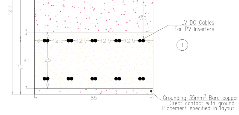
According to your sketch there are two single core cables touching but without any pipe [or duct].
[so Rsd=0 and 110 cm depth]. Let’s say the resistivity stays 2.5 K.m/W.
The calculation according to IEC 60287-2-1 is very simple taking into consideration the cable data-conductor diameter 15 mm, insulated core diameter 17.8 mm and the jacket diameter of 21.2 mm.
The ampacity -per each cable-is then 120.7A.
Following DIN-VDE [from ABB vol.11-E-13] table 13-44, for 3 single core cables in triangle, aluminum I=305 A. From table 13-54 for XLPE, 20oC, 2.5 K.m/W, load factor 1[100%] f1=0.81. From table 13-56 for 10 systems 7cm apart f2=0.44. Then for 10 groups of 3 cables we get 305*0.81*0.44=108.7 A