Continue to Site

Eng-Tips is the largest engineering community on the Internet

Intelligent Work Forums for Engineering Professionals

  • Congratulations waross on being selected by the Eng-Tips community for having the most helpful posts in the forums last week. Way to Go!

AS3600 2017 Draft 1

Status
Not open for further replies.
Replies continue below

Recommended for you

Thanks Trenno. I see they've switched the shear design to the modified compression field theory (MCFT) as in the Canadian code (A23.3). Being Canadian I know the MCFT is generally good but has a few murky corners (e.g. crack spacing parameter). I'll be interested to dig in and see Australia's interpretation. Do you know of any other major changes?
 
There seems to be many changes from the 2009 version.

It would seem our designs just got 5% better, given most of the reduction factors have increased by 5% (for example shear phi = 0.75 instead of 0.7).

 
Trenno,

No, the materials got 5% more reliable than they were 40 years ago apparently!
 
cooperDBM - the latest Australian Bridge Code (AS 5100) already has MCF based shear design rules (but if you want to take a look, the draft AS 3600 is available at no cost during the comments phase).

Doug Jenkins
Interactive Design Services
 
The section capacity reduction factor in the current AS 3600 for shear is 0.7 and it has only gone up slightly to 0.75 in the draft. This value is 0.7 in AS 5100.5-2017. The equation for shear in the current AS 3600 is empirical (from test data and fitting an equation to get a lower bound) which explains the use of a low reduction factor. The shear formulation uses the Compression Field Method which is expected to be more accurate and the factor should be larger than 0.7. Unless someone carries out a reliability study to determine a more accurate value to use, using 0.75 in the interim is conservative.

 
It seems like the code no longer allows the option to use a more conservative value of the strut angle Theta V going up to 60 degrees? Does anyone know why this was removed?
 
nonplussed,

Where does it say that?
 
Clause 8.2.10 in AS3600-2009. The theta angle in the old method is just an assumption, usually 45 degrees. In the new draft the MFCT calculates the specific theta angle that satisfies equilibrium given the actual state of stress on the section. It's usually less than 45 degrees.
 
CooperDBM,

I meant in the Draft! 8.2.4.2 will allow theta up to 50 degrees based on a strain of .003. And it does allow the designer to use a value > than the calculated equilibrium value but no greater than 50 degrees. As you suggest, the model is based on the Canadian MCFT and the theta chosen is more logical than the old method. RAPT has been using the minimum value depending on level of shear compared to Min and Max for many years, so normally significantly less than 45 degrees and often as low as 30 degrees.
 
In 8.2.4.2 I don't see how the designer can control theta other than controlling the level of reinforcing and prestress (e.g. the long. strain). Is that what you mean?
 
cooperDBM,

The last paragraph of 8.2.4.3

"kv and thetav may be determined from Clause 8.2.4.2 using a value of εx that is greater than that
calculated from the equation in this clause. The mid-depth strain parameter εx shall not be
greater than 3.0 * 10-3."
 
Rapt, yes I see it now. They really should have added that clause with the Theta V equation instead of inside a separate clause. Or better yet, just simply stated an optional maximum of 50 degrees. Even now I occasionally use 60 degrees when I have longitudinal steel development issues.
 
That is then section on the calculation of ex, so it is logical to put the upper limit on it there.

It is not technically a limit on theta, it is a limit on ex, which is used to calculate theta and then kv
 
Bit late to the table on this one. Public Comment period closed but...

Does anyone know the intent of <Table2.2.2> (j) "Bending, shear and axial force in singly reinforced walls forming part of a primary lateral load resisting system" resulting in theta=0.65.

I interpret the "primary" to mean walls subject to in-plane shear/structural wall action and NOT out-of-plane actions (i.e. face loading of slender walls)

Cheers
Toby
 
Toby43

I think "primary lateral load resisting system" might give it away!
 
rapt
True, pure semantics - but in my book out-of-plane resistance is of primary concern in resisting lateral loads.
I assume the reduction for singly reinforced walls relates to the lack of confinement in the "boundary elements".
What of seismic 100% in-plane loads coupled with 30% out-of-plane and vice-versa, which would seem reasonable in that out-of-plane action of walls must contribute to action perpendicular to them, which they may have demand placed upon them from buildings torsional response. Also "primary lateral load resisting" elements located at a building corner will receive in-plane demand and out-of-plane demand form wind loads.
So my take on this would be to reduce in-plane response mechanisms by theta=0.65 (when acting alone)
and to reduce out-of-plane response mechanisms by theta=0.8 (Class N reo) - out-of-plane buckling a consideration for effective struts from in-plane action coupled with direct out-of-plane actions.
Example
A typical rectangular tilt building with large opening in wall on "short" side.
The wall "pier" will be subject to in-plane demand from actions parallel to "short" direction of building and out-of-plane actions from "header" over in a tributary sense....
Got called away - may give it more thought and get back later

Cheers
Toby
 
Back...

What I was getting at essentially was that are we to "blanket" all singly reinforced walls with theta=0.65, or only when the bending, shear and axial forces are considered as "in-plane" actions.
Back to tilt up buildings - it would seem unreasonable for a wall subject to out-of-plane bending, with N-class reinforcement that meets the minimum ratios and demands to be assigned theta =0.65. Essentially a wall designed utilizing the findings of the slender wall task committee and SEAOC bluebook recommendations should be sufficiently reliable with theta =0.8-0.9.
Maybe too many tilt panels have been designed ignoring minimum steel quantities, with L class reinforcement and neglect of P-Delta effects, that theta=0.65 is warranted. In my opinion such poorly designed walls would need more than theta=0.65 to make them sufficiently reliable.

Toby
 
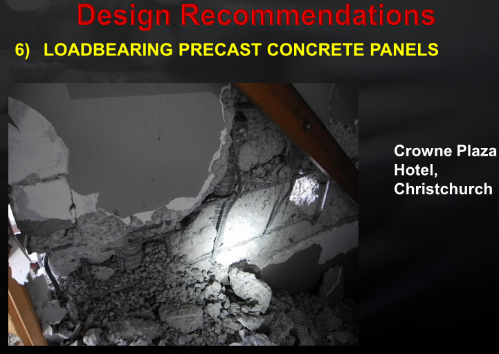
I think the low theta for singly reinforced walls came from the observed performance of these walls in the Christchurch earthquake.

1_nqpkjz.png
 
Trenno - Granted, yet theta=0.65 for a out-of-plane would not seem reasonable.

If this blanket theta applies to out-of-plane actions then 2 identical walls in every way, except one has L class and the other N class, would be "rated" the same.

 
Status
Not open for further replies.

Part and Inventory Search

Sponsor