Continue to Site

Eng-Tips is the largest engineering community on the Internet

Intelligent Work Forums for Engineering Professionals

  • Congratulations KootK on being selected by the Eng-Tips community for having the most helpful posts in the forums last week. Way to Go!

Applying datum shift to profile tolerance with a MMB on a midplane 1

Status
Not open for further replies.

cheezhed321

Mechanical
Jan 28, 2016
6
Hi,

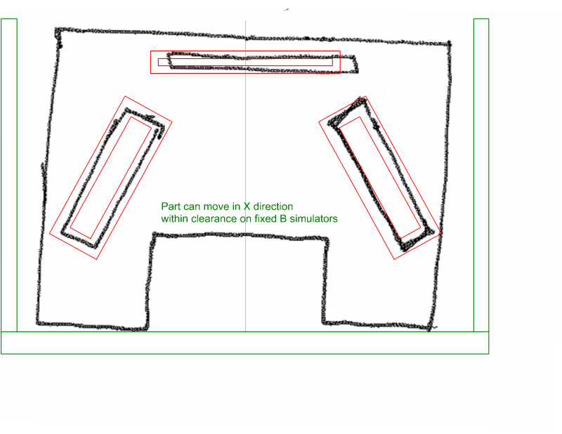
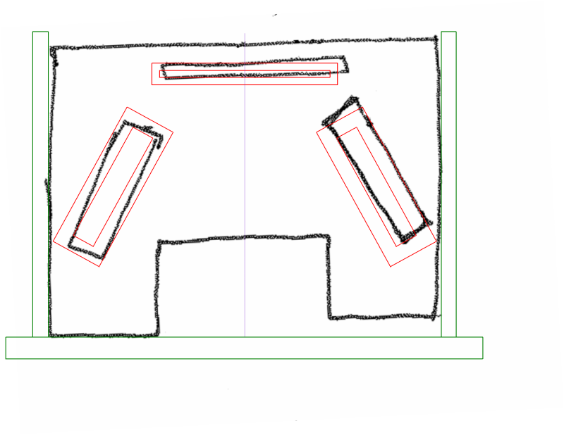
I am pretty new to the applications of GDT. I have been reading books and such to learn at my new job, but one thing hard for me to comprehend has been how to use the MMB that follows a datum in a FCF when that datum is a plane or midplane. For example, attached is a more basic representation of a part I am working with (apologizes for the crudeness but hopefully it gets the point across). The slots have a profile tolerance associated with them that call them back to datum A, B and C; however, B has an MMB modifier associated with it. I am not sure how to apply this to the slots' tolerance. I understand that it does not give bonus tolerance to the .005 but I'm not sure where it comes into play especially when datum B is a mid plane. Does its size really change even when the width increases or decreases? And if so, how does it affect the slots? I guess it is some kind of shift but I'm just not sure how you would apply it.

please let me know if you require any more information.

Thanks.
 
 http://files.engineering.com/getfile.aspx?folder=361c51bf-77e1-4527-be08-21e743c8ffba&file=20160128091122962.pdf
Replies continue below

Recommended for you

cheezhed321,

Here's what you get:

Profile_Tol_with_Datum_B_at_MMB_opinfp.png


You're right that the MMB reference on B doesn't make the profile tolerances zones any larger. It makes the datum feature simulator for B a fixed width, which allows "datum feature shift" if feature B is produced smaller than its maximum. The shift can be used to try to get all of the slots to line up with their tolerance zones (which are fixed relative to the datums). But by default they all have to line up at the same time - you can't shift one way for one zone and shift a different way for the others. Hope this helps.

Evan Janeshewski

Axymetrix Quality Engineering Inc.
 
Axym,

Great explanation.. I actually understand!
I have 2 follow up questions:

1. if the MMB on datum B was not there, the the datum feature simulator or gage would just have to clamp down on the width of B?
2. With what you have drawn above, the part can shift to try to fit the slot features, but can it shift away from Datum C (the wall perpendicular to the 2 walls for datum B)?

thanks,
 
cheezhed321,

1. Yes. The two faces of the B simulator would move to the minimum separation that would still envelop the B feature. This will rotate the part as well.
2. The part must stay in contact with simulator C, with at least one point of contact.

Here is the scenario if B was not at MMB (i.e. was at RMB):

Profile_Tol_with_Datum_B_at_RMB_rbnpcr.png


Evan Janeshewski

Axymetrix Quality Engineering Inc.
 
axym said:
2. The part must stay in contact with simulator C, with at least one point of contact.

Is that the only requirement, or must it make the maximum contact allowed by the higher precedence datum feature references? ASME Y14.5-2009 Fig. 4-21 illustration (c) shows maximum contact, but I haven't found a clear answer in the text.

- pylfrm
 
pylfrm,

This is a bit of a gray area. That figure does imply maximum contact.

Have a look at Fig. 4-30 b) and Section 4.16.4. The text states that contact on the secondary datum feature simulator is not necessary.

Evan Janeshewski

Axymetrix Quality Engineering Inc.
 
axym,

Understood. Thanks for pointing out Fig. 4-30. Comparing that and Fig. 4-31 reminds me that datums sometimes get rather more complicated than I usually have to worry about. Lots of special cases it seems.

- pylfrm
 
Evan,
May I ask you why in fig 4.29b and 4.30b the contact is not required, but in Fig 4.31c the contact is required in a minimum one point? For me the concept in 4.31c is similar to the one in 4.29b and 4.39b, but the way the datum feature simulator acts is different. Y14.5-2009.
 
greenimi,

I believe that this has something to do with opposition and containment. The opposed simulators in 4-29 and 4-30 limit the rotational motion in both directions, but the unopposed simulator in 4-31 only limits rotation in one direction. If the requirement for single-point contact was not present, then the part in Fig. 4-31 (c) would have almost unlimited rotation in the counterclockwise direction.

Evan Janeshewski

Axymetrix Quality Engineering Inc.
 
That can be confirmed in the standard.
The contact is not required in 4-29(b) and 4-30(b) because the rotation would be restricted when rotating the part in either direction. From the section referencing 4-31(c):

4.16.7 . . . Where the datum feature simulator and the higher precedence datum axis do not limit rotation in both directions about the datum axis, the datum feature must always contact the datum feature simulator.​
 
Ref 4.29, 4.30, 4.31

So, it is more complicated as initially I thought. Someone for sure will say, it is complicated because the life/ the parts/ assemblies are complicated.
I have to say it that I am not sure if the general industry (not military, aerospace or medical) is ready or will understand these specific callouts with the applicable level of details (or will perceive that is a difference between the way the parts are inspected, even they should)
The gap between the real world and the theory will just increase.
 
Status
Not open for further replies.

Part and Inventory Search

Sponsor