I have a old 84’x120’x17’ tall masonry wall building with a metal roof deck on bar joists. The roof covering is tar and gravel. The building is probably at least 40 years old or more.
My Client wants to remove the exterior 12” hollow block wall that runs parallel to the bar joists. I went out and looked to see how the building was originally constructed. I am sure the interior frames are not rigid frames and not fixed base columns. I am a little puzzled by what I have seen so far and was wondering if anyone had any thoughts about how this system was supposed to work. Here is what I know:
• The building is a simple 4-side masonry box. The block walls parapet on 3 sides.
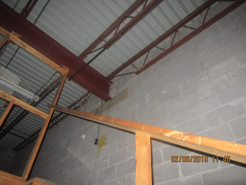
• The interior frames run the 120’ direction and the end of the roof beams set on the 84’ hollow block walls. There are no roof rods, x-bracing, portal frames, K-bracing etc present anywhere.
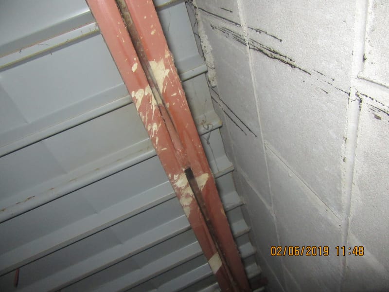
• There is no visible connection of the bar joists or the underside of the metal deck to the parapet block wall on the 2 walls that are parallel to the bar joists. I can see up the full depth of the 1.5” roof deck and see no connection from the wall to the roof panel or roof structure. After the 1.5” metal deck, I cannot see anything. 1" Insulation and tar block anymore view.
• The only portion of the roof that definitely connects to the block wall is the ends of the 2 roof girders. They set at the 3rd points of the 84’ block wall.
• The masonry walls have no bond beams on the walls parallel to the bar joists. The other 2 walls I am not sure about.
• The roof definitely is not concrete, it is tar and gravel.
Bear in mind, where I live, we have some of the lightest design loads and actual loads. For that reason, poor designs can still stand up because they rarely get tested. I think the highest wind we have had in years was around 58 mph in the old way of measuring wind. At that point in time, the older codes made this a 70 mph design. In the old code, 10 psf was the total wind to the MWFRS. So 58 mph would be about 7 psf. Also in my location, architects have been allowed to do entire building designs via the “allowed to do engineering incidental to architecture” clause. Our actual seismic is non-existent for all practical purposes. I am less than 100 miles from a seismic zone 0 in the old codes.
My original thoughts were this is a metal diaphragm roof and 4 masonry shear walls. But not seeing a physical connection of the roof to the sidewalls has me puzzled. I have never seen anyone just use the ends of the girders and the corner masonry wall connections as their only way of transferring shear for wind or seismic. Am I missing the presence of some other system or is this just a poor design that has withstood time? Is there a good way to connect the roof to the walls from above the metal deck that I do not know of?
My Client wants to remove the exterior 12” hollow block wall that runs parallel to the bar joists. I went out and looked to see how the building was originally constructed. I am sure the interior frames are not rigid frames and not fixed base columns. I am a little puzzled by what I have seen so far and was wondering if anyone had any thoughts about how this system was supposed to work. Here is what I know:
• The building is a simple 4-side masonry box. The block walls parapet on 3 sides.
• The interior frames run the 120’ direction and the end of the roof beams set on the 84’ hollow block walls. There are no roof rods, x-bracing, portal frames, K-bracing etc present anywhere.
• There is no visible connection of the bar joists or the underside of the metal deck to the parapet block wall on the 2 walls that are parallel to the bar joists. I can see up the full depth of the 1.5” roof deck and see no connection from the wall to the roof panel or roof structure. After the 1.5” metal deck, I cannot see anything. 1" Insulation and tar block anymore view.
• The only portion of the roof that definitely connects to the block wall is the ends of the 2 roof girders. They set at the 3rd points of the 84’ block wall.
• The masonry walls have no bond beams on the walls parallel to the bar joists. The other 2 walls I am not sure about.
• The roof definitely is not concrete, it is tar and gravel.
Bear in mind, where I live, we have some of the lightest design loads and actual loads. For that reason, poor designs can still stand up because they rarely get tested. I think the highest wind we have had in years was around 58 mph in the old way of measuring wind. At that point in time, the older codes made this a 70 mph design. In the old code, 10 psf was the total wind to the MWFRS. So 58 mph would be about 7 psf. Also in my location, architects have been allowed to do entire building designs via the “allowed to do engineering incidental to architecture” clause. Our actual seismic is non-existent for all practical purposes. I am less than 100 miles from a seismic zone 0 in the old codes.
My original thoughts were this is a metal diaphragm roof and 4 masonry shear walls. But not seeing a physical connection of the roof to the sidewalls has me puzzled. I have never seen anyone just use the ends of the girders and the corner masonry wall connections as their only way of transferring shear for wind or seismic. Am I missing the presence of some other system or is this just a poor design that has withstood time? Is there a good way to connect the roof to the walls from above the metal deck that I do not know of?