Hi All,
It seems that each of us is focusing on different details and their importance, but I think that we're generally in agreement.
CH,
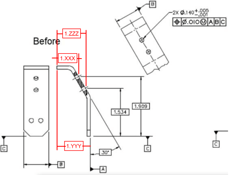
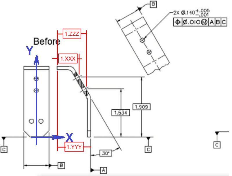
OK I think I see it now. The Before scheme does not provide enough dimensions to fully define the required geometry, and the After scheme does. With only a Y coordinate for one endpoint of each axis, we don't know where the axes are in the X direction. If we wanted to build a gage to check the position tolerance, we couldn't do it using the dimensions in the Before drawing But we could build a gage using the After drawing. So I agree that from a completeness standpoint, the Before scheme is insufficient and the After scheme is sufficient. Sorry for not seeing that earlier - 3DDave pointed it out as well.
As far as what type of basic dimensions can be used, I would still maintain that the essential thing is that the relationship between the toleranced feature(s) and the datum feature(s) is fully defined. Many different arrangements of basic dimensions could accomplish this. But I would also agree that certain arrangements would be more direct and clear to the typical reader, and other arrangments would be less direct, unclear, and convoluted.
Here is an example. I've added extra dimensions to the Before scheme to make it complete (please forgive the poor drafting technique - I'm not an expert on drawing layout and drafting).
I would say that this dimensioning scheme is adequate, but perhaps somewhat indirect. The dimensions involve the left-hand end surface that is not a considered feature or a datum feature for the position tolerance, and this may be distracting or confusing to many readers. But including dimensions to this surface does not cause any fundamental issues or make the scheme meaningless, because the dimensions are all basic anyway. It doesn't mean that we have to line up on the left-hand end surface on the real part.
Evan Janeshewski
Axymetrix Quality Engineering Inc.
![[bigsmile]](/data/assets/smilies/bigsmile.gif "[bigsmile] [bigsmile]")
![[glasses]](/data/assets/smilies/glasses.gif "[glasses] [glasses]")