Continue to Site

Eng-Tips is the largest engineering community on the Internet

Intelligent Work Forums for Engineering Professionals

  • Congratulations The Obturator on being selected by the Eng-Tips community for having the most helpful posts in the forums last week. Way to Go!

Anchorage into a mat slab foundation 7

Status
Not open for further replies.

JoshPlumSE

Structural
Aug 15, 2008
10,579
This isn't related to work that I do directly. But, rather a technical issue that I was helping someone else with. And, I realized I didn't have a great solution. I'm curious what I'm missing or what other options are available.

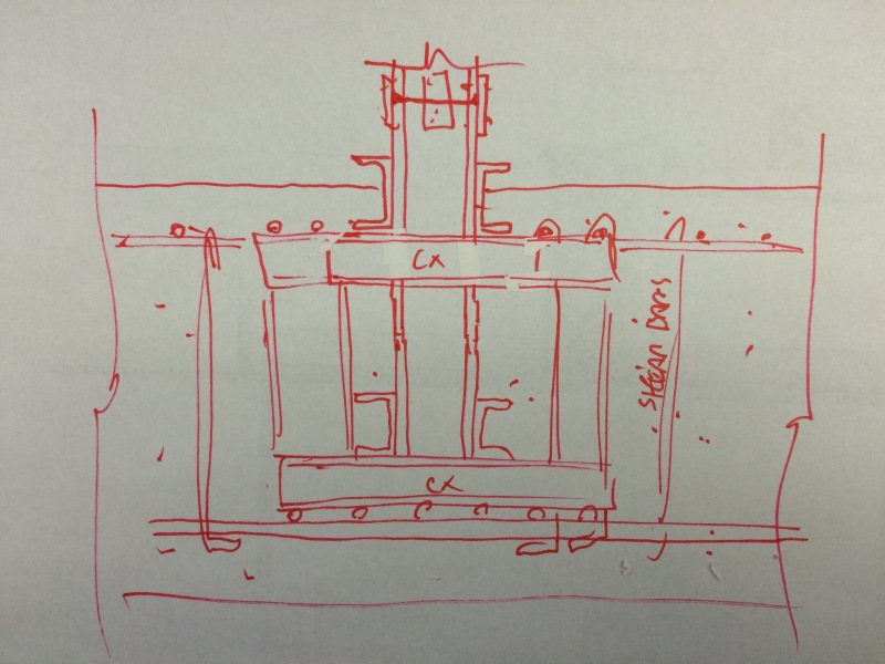
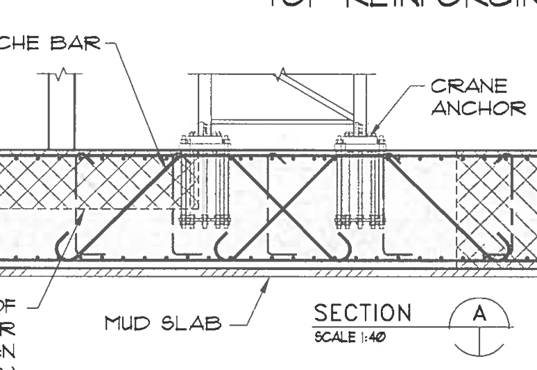
They had a steel SMF frame coming down directly onto a reasonably thick mat slab foundation (36~48"). Some relatively shallow (4") pockets so that the slab surface would be undisturbed by the base plates or stiffeners or such. The pockets aren't particular important except they lead to question #1:

Question #1: Does the presence of these pockets reduce the pullout cone strength of the rods. My thought was no. Provided the pullout cone extends beyond the width of the pockets.

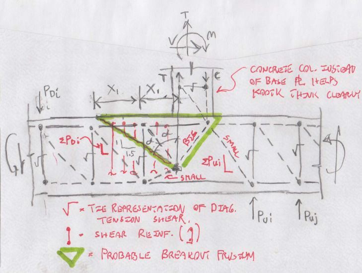
Now, because it was a moment connection there were huge tension forces that needed to get developed from the anchor rods into the concrete slab. Embedment depth of the headed anchors wasn't going to be enough. So, the project would need some kind of supplemental reinforcement to resist the anchorage forces.

Question #2: What type of supplemental reinforcement to add?

There is plenty of horizontal bars in the slab that would intersect the pullout cone. But, I don't know whether those bars can be considered to resist it or not. Maybe a stud rail like you would use to resist a punching shear failure?

I am a number of years removed from true design engineering. But, even so, I am disappointed that I didn't fully grasp the solution to what should be a pretty common engineering issue these days.

 
Replies continue below

Recommended for you

If you are trying to get fixity at the base and they are large moment frames. Embed the column into the mat and provide reinforcing in the slab. AISC Seismic Manual has a sample of both designs, embed is on 4-119.
 
I've got 10 scratch scratch sheets on this just trying to get my head around it -

I think this arrangement makes more sense at the anchor head due to symmetry. I've also kept the theoretical ties orthogonal although I imagine the ties would be perpendicular to the splitting plane - a direction that makes the STM even more confusing. With this arrangement I can better visualize the moment compatibility through the depth of the footing (moment at the bottom of column = moment at the bottom of the anchorage.


EMBEDTO_FTG_e0b6dy.jpg
 
Excellent idea Sandman.... I actually thought of that originally. But, I didn't take it very far. The owner / developer didn't like the idea. And, it was unconventional enough that I wasn't going to push for it.

But, now I'm going to read through that example some more to make sure I understand it as well.
 
In a mat its even easier to do than in grade beams, as you have more space to move bars. It will require less reinforcing than anchor bolts as you are using material that already needs to be there. The additional reinforcing is minor compared to the trying to get App. D to work. The connection will get a little messy close to the edge of the mat.

We only use base plates when we have small OMF's or assuming pinned base. Larger moment frames the base plate is significantly more expensive, 2" 50ksi plate, stiffeners, 10 - 2" 105ksi bolts, to build and install. The add benefit is that you are also closer to a fixed connection and have less drift.
 
@sandman: usually the objection that I get regarding embedding in a raft is difficulty in accurately setting and plumbing the columns. In that respect, a grade beam spanning over pad footings or piles seems to be much more palatable. How do you deal with this for the raft scenario?

@Teguci: I had to stare at your strut and tie model for a good twenty minutes before I fully grasped the subtlety of what you did there. It's brilliant. Creating a strut and tie model patterned after an Appendix D breakout failure really elucidates things. After mulling it over for a few days, I took the liberty of attempting to refine and improve your model. My thinking was as follows:

1) Your STM suggested a breakout frustum slightly different from the one that I proposed earlier. I adjusted the model to reflect my assumptions regarding the breakout frustum. I believe that it would be inherently asymmetrical about the tension anchor.

2) With #5 or smaller ties wrapped around longitudinal bars, I believe that it's fair to move your point "A" up to the top of the raft. This simplifies the model some.

3) I moved your point "C" up to the top of the raft and adjusted the last strut coming in from the right to hit that same point. This is consistent with my expectations regarding the compression stress trajectories in these areas.

4) I've got a compression field arching from the column/base plate compression zone all the way down to the bottom of the raft. Most of the compression would be absorbed into the tension anchor as the strut passes by.

Also, I finally figured out what you've been doing with that "v" shaped symbol that you draw over your ties that are represented by Vc. It represents SQRT(f'c), right? I'm adopting that from this point forward.

capture_wjphuy.jpg


I like to debate structural engineering theory -- a lot. If I challenge you on something, know that I'm doing so because I respect your opinion enough to either change it or adopt it.
 
I have done it a couple ways: provided construction pad footings with base plates to set the columns on below the mat, designed grade beams above the mat foundation and have a base plate sit on the top of the mat foundation.

I have seen others weld on members (Cx) to the sides of the columns they then provide reinforcing to support the column.
 
Thanks for the clarification sandman. Could you elaborate a bit more on the last option? Two channels welded to the sides of the column and then...

I like to debate structural engineering theory -- a lot. If I challenge you on something, know that I'm doing so because I respect your opinion enough to either change it or adopt it.
 
To set the height of the Wx and check the column plumb they will weld a two or three foot piece of Cx to the flanges going in both directions near the bottom and top or as requried. They then set the Cx longitudinal bars while also tie to shear reinforcing, you can add as many Cx as need to keep the Wx secure. The provide I saw it on use the mat reinforcing and the contractor added some additional reinforcing to help. They only had the first splice at the first floor to limit the weight of the column.
 
Like this? I must have something wrong as I can't imagine one would leave any of the channels sticking up out of the footing.

image_wal6fc.jpg


I like to debate structural engineering theory -- a lot. If I challenge you on something, know that I'm doing so because I respect your opinion enough to either change it or adopt it.
 
That's the basic idea but without the Cx sticking out, they will add a layer of reinforcing, below the top mat reinforcing for the top Cx to sit on. I have seen this in deeper mat foundations, 8'+
 
Neat. I still find it surprising that one could install the embed that way, pour a bunch of concrete around it, and still be confident that the final position would be within tolerance. This shall be a new tool in my kit. Thanks for walking me through it sandman.

I like to debate structural engineering theory -- a lot. If I challenge you on something, know that I'm doing so because I respect your opinion enough to either change it or adopt it.
 
I make no warranties or guarantees as I have only seen the drawings for it. It makes sense to me and like I said it was on a large mat foundation with several layers of reinforcing for bending and shear, so it had three rows if I remember correctly.
 
Oh no, I'm doing this now and referencing sandman21 (interweb weirdo) in my specifications.

Honestly, I'm amazed that anyone can actually build anything. In an effort to "keep it real", I joined a local trade school masonry lab once. I built a 4' lintel over two courses of wall pier. It took me a whole afternoon and wasn't even remotely within spec. In fact, had there been a job site supervisor, he or she would have been remiss to not have asked me for blood testing.

I like to debate structural engineering theory -- a lot. If I challenge you on something, know that I'm doing so because I respect your opinion enough to either change it or adopt it.
 
Only fair since you are referenced in my calculations. ;)

I just dont know if the contractor made them change the design or what. So your work sounds about right for what I have been seeing lately.
 
Did a little reading up on related issues last night: Link. The benefit of a moment induced compression force on the breakout frustum has been studied. I thought it prudent to share for the sake of others who might be interested.

In summary:

1) Work done by Zhao in 1993. I couldn't get my hands on the original stuff.
2) As expected, for the right combinations of lever arm versus embedment depth, there are marked improvements.
3) There's a proposed evaluation method but it requires determining a parameter (z) based on an elastic analysis. Not sure what to do with that in practice.

Capture02_wjrco7.jpg

Capture01_eqbope.jpg

Capture03_ivm8s7.jpg


I like to debate structural engineering theory -- a lot. If I challenge you on something, know that I'm doing so because I respect your opinion enough to either change it or adopt it.
 
I just can't get enough of this thread for some reason. Some crane base shop drawings crossed my desk this morning with a familiarly looking pullout detail. I'd have to think that such a setup is probably getting taxed quite heavily, and quite frequently, compared to a building's lateral system. Footing depth = 1400 mm. The stirrups that you see are cal lout out as "bar support". I'm not sure if they're intended to pull double duty.

Capture_oupnzb.png


I like to debate structural engineering theory -- a lot. If I challenge you on something, know that I'm doing so because I respect your opinion enough to either change it or adopt it.
 
Australian structural engineering never ceases to amaze... Their modified failure cone is actually more aggressive than the one that I proposed.

I like to debate structural engineering theory -- a lot. If I challenge you on something, know that I'm doing so because I respect your opinion enough to either change it or adopt it.
 
KootK said:
Australian structural engineering never ceases to amaze.

The Ancon brochure referenced by bookowski is actually from the UK, but Ancon are very active in AU.

Us Aussies are just a country of convicts :)

 
My bad. Let's reassign those cudos to Scotland then. Nice work Scotland.

I like to debate structural engineering theory -- a lot. If I challenge you on something, know that I'm doing so because I respect your opinion enough to either change it or adopt it.
 
Status
Not open for further replies.

Part and Inventory Search

Sponsor