Continue to Site

Eng-Tips is the largest engineering community on the Internet

Intelligent Work Forums for Engineering Professionals

  • Congratulations The Obturator on being selected by the Eng-Tips community for having the most helpful posts in the forums last week. Way to Go!

Anchorage into a mat slab foundation 7

Status
Not open for further replies.

JoshPlumSE

Structural
Aug 15, 2008
10,578
This isn't related to work that I do directly. But, rather a technical issue that I was helping someone else with. And, I realized I didn't have a great solution. I'm curious what I'm missing or what other options are available.

They had a steel SMF frame coming down directly onto a reasonably thick mat slab foundation (36~48"). Some relatively shallow (4") pockets so that the slab surface would be undisturbed by the base plates or stiffeners or such. The pockets aren't particular important except they lead to question #1:

Question #1: Does the presence of these pockets reduce the pullout cone strength of the rods. My thought was no. Provided the pullout cone extends beyond the width of the pockets.

Now, because it was a moment connection there were huge tension forces that needed to get developed from the anchor rods into the concrete slab. Embedment depth of the headed anchors wasn't going to be enough. So, the project would need some kind of supplemental reinforcement to resist the anchorage forces.

Question #2: What type of supplemental reinforcement to add?

There is plenty of horizontal bars in the slab that would intersect the pullout cone. But, I don't know whether those bars can be considered to resist it or not. Maybe a stud rail like you would use to resist a punching shear failure?

I am a number of years removed from true design engineering. But, even so, I am disappointed that I didn't fully grasp the solution to what should be a pretty common engineering issue these days.

 
Replies continue below

Recommended for you

On question 1, I agree with you that as long as the pocket does not intercept the plane of the failure cone, it should not reduce the pullout capacity (but it may reduce the capacity of other failure modes). That said, even if it did intercept the failure cone and did not pass, I would want to re-think the connection because if that was the straw that broke the camel's back, the design was probably barely passing anyway.

On question 2, you can add supplemental steel as long as it is developed on both sides of the failure plane. That can be tricky because of limited space for bar development. Also, that steel should not serve double duty unless its designed to do so (i.e. flexural steel in the mat and supplemental steel to resist pullout)
 
#1) I'm fairly certain that it would make little difference. That said, I would tend towards conservatism here. If you envision the situation in STM terms, it becomes a bit disconcerting to be counting on a bunch of concrete placed above your top steel. On the other hand, if the pocket is very small relative to your projected failure cone, then chances are that most of the useful top steel will be located at the "normal cover" elevation rather than the "below the pocket" elevation.

#2) If extending the anchor bolts to the bottom of the footing wasn't getting the job done, I'd do one or all of the following:

a) Thicken the footing locally below the anchors to get a larger failure frustum.

b) Install an embedded steel plate bolted to the anchors at the bottom of the footing such that I could call the tension failure mode upside down punching shear.

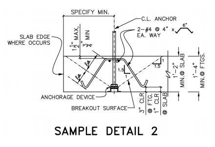
c) If upside down punching shear doesn't work, add "candy cane" rebar ties in a uniform pattern about the anchors extending out until punching shear does work (just like a column terminating at a transfer slab).


I like to debate structural engineering theory -- a lot. If I challenge you on something, know that I'm doing so because I respect your opinion enough to either change it or adopt it.
 
So, let's say you add some supplemental reinforcement to the top slab above and beyond what is required in that slab. My thought is that the angle the top slab reinforcement makes with pullout cone would be too steep to really transfer the tension into the bar.

Therefore, we'd have to do one of the following:
1) Bend the bars down at approximately 45 degrees (truss bars) at approximately where they would intersect the pullout cone. Then lap them with bottom bars.

2) Add in some vertical shear ties in that region like there is a grade beam contained within that slab. The vertical nature of the ties will intersect the pullout cone and transfer that tension into this pseudo grade beam.

3) Same concept as #2, but using some type of stud rail system. Thinking that the concept of punching shear and this type of pull out cone are basically the same.

 
Last post written before KootK's candy cane bar response. My same concern with these candy cane bars as I have for the supplemental bars in the top of the slab. The angle is perpendicular to the original tension force that we're trying to resist. Can we really rely on horizontal bars like this for the supplemental reinforcement.

I hadn't thought of an embed plate at the bottom. Not a bad idea. But, doesn't it seem odd that this would give me so much more capacity than just the anchors. The pullout cone is basically the same dimensions as punching shear would have been. I know it's true though because this slab worked fine for punching shear.
 
The candy cane bars that I mentioned would be vertical. Basically, the construction friendly slab version of stirrups.

I like the truss bars in concept. I've seen some wood shear wall to slab tie down details published by Washington state that are very similar, just on a smaller scale. My only concern would be coming up with a numerical evaluation method that seemed "official" enough.

I like the mini grade beam idea too. That might in fact be the most constructible solution. Basically shear heads done in concrete.

I would think that the embed plate would produce the same failure cone. And one probably could just use plain headed anchors. I basically just go with the plate to produce a situation that I feel confident about with regard to its similarity to something accepted (punching shear).

I like to debate structural engineering theory -- a lot. If I challenge you on something, know that I'm doing so because I respect your opinion enough to either change it or adopt it.
 
If it's a moment connection aren't you looking at roughly equal tension and compression force, or is there a lot of net uplift?

Plate on the anchor bolts is common for developing the anchors. Shear reinforcing would normally be vertical. Bent bars seem to make more sense but you don't see them often, presumably for constructability reasons. I think that aci 421 recommends additional reduction factor if using rebar instead of headed anchors for shear in mats.
 
It is moment, that's true. There was some net uplift, but it wasn't huge compared to the tension caused by the moment.

I'd always looked at the anchorage requirements on the tension side as being independent of the compression on the other side. Are you suggesting that the embedded plate connected to the anchors would inherently transfer the moment without requiring that we design tension anchorage? Essentially doing what KootK said, and simplifying this down to a punching shear calculation.

If so, that actually makes me feel a lot better. These anchorage calculations seem so complex these days (compared to when I did them 15+ years ago at my previous employer). Relating it back to a a different failure method (punching shear) that I feel much more comfortable with brings me closer to first principles and expected behavior.... Rather than trying to shoe-horn my situation into matching code equations that were derived for single anchors acting independently.
 
I don't know about the embed plate transferring the moment without considering tension anchorage. I would feel comfortable with the plate (if very rigid) to resist the tension component in the form of punching shear as an alternate to App D calcs. Or develop the force into new rebar.
 
The common method for anchor bolts is to plate each bolt. This gives, potentially, 4 overlapping failure cones in the concrete....complicated to resist with rebar.

Consider the following....

A full plate that engages the bottom of all bolts, with a large hole in the center to allow continuity of the concrete flowing around and through the plate. This allows a very large failure cone that will have a large pullout resistance because of the larger shear area on the concrete and reduced shear stress as a result.

or....

A very stiff bottom plate of expanded metal that allows a lot of concrete paste continuity and interlock as well as promoting a larger shear failure cone as noted above.
 
These are those smaller scale details that I mentioned that are eerily similar to your ideas.

capture_w1latn.jpg


Capture_2_xk5iy5.jpg


I like to debate structural engineering theory -- a lot. If I challenge you on something, know that I'm doing so because I respect your opinion enough to either change it or adopt it.
 
Book said:
If it's a moment connection aren't you looking at roughly equal tension and compression force, or is there a lot of net uplift?

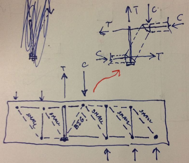
I agree with what I think you're getting at. If the anchors are long enough I think that you get a situation as shown in the sketch below where the lion's share of the tension is countered by the applied compression from the moment couple. The moment largely gets resisted by horizontal force mechanisms in the footing which makes sense as base plate moment must ultimately be converted into footing moment.

JP said:
I'd always looked at the anchorage requirements on the tension side as being independent of the compression on the other side.

I've done a lot of this too mostly just because you don't see much about this alternate path in the literature. From what I've seen most designers look at the tension anchorage independently.

capture_gvu9um.jpg


I like to debate structural engineering theory -- a lot. If I challenge you on something, know that I'm doing so because I respect your opinion enough to either change it or adopt it.
 
I wouldn't use the compression component method to justify a new anchorage to concrete design. I would stay with what is more conventional.
 
Hey KootK....great minds think alike!....[rofl]
 
With regard to question #2, I have often added vertical rebar, developed on both sides of the failure plane, adjacent to each anchor rod to avoid having to check concrete breakout strength for tension loading. This is explicitly permitted in ACI 318-11 D.5.2.9. A graphic of this condition is shown in Figure RD.5.2.9 in ACI 318-11. I typically use 90-degree or 180-degree hooks on the top and/or bottom if development length is a problem. The center-to-center spacing of the added rebar and the anchor rods must be less than or equal to 50% of the embedment depth (hef) per ACI.
 
Hokie said:
With regard to question #2, I have often added vertical rebar, developed on both sides of the failure plane, adjacent to each anchor rod to avoid having to check concrete breakout strength for tension loading.

I've two, related concerns with this:

1) My impression is that app D, and the supplementary reinforcement business shown in RD5.2.9 in particular, is intended for small scale stuff. For the implied case of something like a curtain wall anchor, it's reasonable to assume that the supplementary reinforcing might double or triple your breakout capacity and can therefore just be deemed to be sufficient once the supplementary reinforcement has been provided. I think that a tension connection between a primary frame column and a foundation warrants more rigor.

2) With the supplementary reinforcement, all that you're effectively doing is lengthening the anchor bolts. There's still a breakout frustum to be checked, it's just a larger, more difficult to define frustum. Its a bit worse that lengthening the anchor bolts really because your anchorage occurs faster with heads/plates than it does via rebar knurl engagement.

I like to debate structural engineering theory -- a lot. If I challenge you on something, know that I'm doing so because I respect your opinion enough to either change it or adopt it.
 
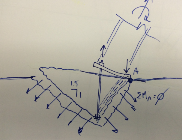
If App D wants to be the way and the truth and the light, I really feel that it needs a version of the breakout mode shown below. I've tinkered with it for sport and the results have turned out ver6y promising numerically. I've yet to implement it in practice, however, because I feel as though it's a stretch to be making this stuff up myself given all of the research effort it took to get us appD.

Capture_dlmmqj.png


I like to debate structural engineering theory -- a lot. If I challenge you on something, know that I'm doing so because I respect your opinion enough to either change it or adopt it.
 
I just want to thank everyone who commented. The issue is a lot more clear and rational in my mind now.

In my case, I'd probably go with something akin to KootK's "Sample Detail 2". But, where the bar then laps with the bottom bars for some significant length. Seems like the simplest way to detail it when the mat isn't too congested and you have room to develop those bars.

And, for what it's worth, the discussion of moment and Strut-Tie method really helped as well. Just as a means of bringing the discussion back to first principles. I think that's really where I was having issues with the anchorage calculations. The code requirements are not unclear if you're talking about a single bolt or a group of bolts in pure shear or pure tension. But, moment and anchorage reinforcement (to resist that moment) were the aspects that weren't making sense to me.

Thanks again everyone!


Status
Not open for further replies.

Part and Inventory Search

Sponsor