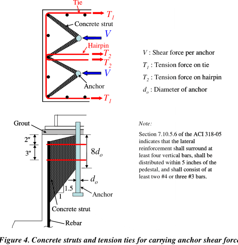
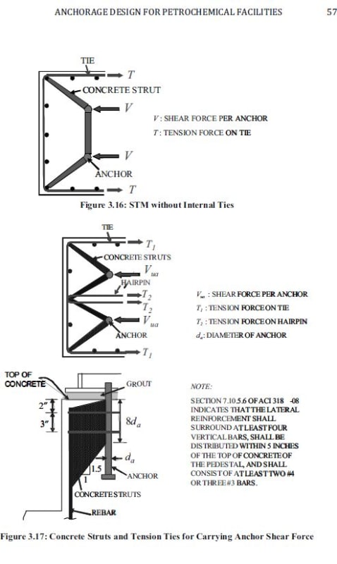
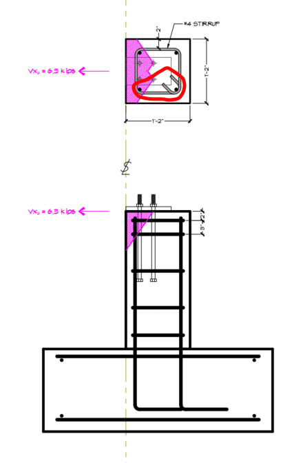
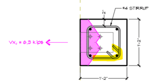
3. For tie reinforcement, and with reference to Figure 3.18, the following assumptions are suggested:
a. Only the uppermost two layers of ties (assume two #4 ties within 5 in. (127 mm) of the top of the pedestal as required by ACI 318 Section 7.10.5.6) are effective.
b. Tie reinforcement should consist of ties with seismic hooks. If internal ties are required, hairpins could be used. As an alternative, diamond-shaped ties can also be used.
c. The location of hooks and the direction of hairpins should be alternated as shown.
d. If the available development length of hairpin, ldha, is shorter than the required straight development length for a fully developed hairpin, ldh, the maximum yield strength that can be developed in a hairpin is: Fy x ldha/ldh
where Fy is the yield strength of the hairpin. If ldha is shorter than 12 in.(304.8 mm), (that is, the minimum development length based on ACI 318 Section 12.2.1), then a hairpin should not be used.
e. Away from the hook, the tie is assumed to be fully developed. For example, under the shear force Vua, the tie on layer A can develop Fy at nodes 1 and 6
f. At the node where the hook is located, the tie cannot develop Fy. For example, under the shear force Vua, while the tie on layer A can develop Fy[/sub at node 6, the tie on layer B cannot, because the hook of the tie on layer B is located at node 6. In order to calculate the contribution of the tie on layer B to the tension tie at node 6, and with reference to Figure 3.19, the stiffness of a hooked bar bearing on concrete (Case 1 - smooth rebar with 180° hook bearing in concrete [Fabbrocino et al., 2005]) is compared to the stiffness of a hooked bar bearing on rebar (Case 2 - the conventional single-leg stirrup with reinforcing bars inside the bends [Leonhardt and Walther, 1965 as cited in Ghali and Youakim, 2005]).
Even though the capacity of Case 2 may be higher than that of Case 1 because of bearing on rebar of a larger size than the stirrup, contact may not always be present because of common imprecise workmanship. When the contact is not present, Case 2 is assumed to behave as Case 1. Leonhardt and Walther (1965) found that in order to develop fy on the bends of 90°, 135°, and 180° hooks when engaging bars located inside the bends (Case 2), there was a slip of about 0.2 mm (0.0079 in.). Based on the test results of Fabbrocino et al. (2005), the stress that was developed at the hook of the smooth rebar with a 180° hook bearing in concrete when it slipped 0.2 mm was about 20 ksi (138 MPa). Therefore, it is assumed that the tie can only develop 20 ksi (138 MPa) at the node where the hook is located.


