Tek-Tips is the largest IT community on the Internet today!

Members share and learn making Tek-Tips Forums the best source of peer-reviewed technical information on the Internet!

  • Congratulations JAE on being selected by the Eng-Tips community for having the most helpful posts in the forums last week. Way to Go!

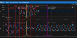
Analyzing a 3-phase fault recorded waveform from an SEL relay on a 15kV feeder breaker, when did the breaker trip, why is VB at 0V before the fault ?

bdn2004

Electrical
Joined
Jan 27, 2007
Messages
809
Location
US
There was fault on this feeder breaker. The instantaneous relay was set at 18000 amps. There was no load on the feeder.
Was the wave decaying on it's own then it tripped ? Or is the last part of the top current wave when the breaker tripped ?

Another question is ... WHY is VB at 0V before the fault ? Is this indicating a ground fault on the B phase ?
The system this is fed from is a 138Y-15D kV ungrounded transformer, but has installed at the first switchgear, upstream from the faulted switchgear, a grounding transformer (15YG-.480D kV) through a 300A, 29ohm resistor.


SG4 Fault Waveform.png
 

"when did the breaker trip"​

I'd guess at about 140 ms. That's when it appears the voltage begins to recover and the currents drop off.

"why is VB at 0V before the fault"​

What was the nature of the fault? It appears that B phase may have been involved first. But due to the grounding transformer and associated resistance, insufficient fault current developed until it developed into a three phase fault.
 
getting a raw report would be useful with higher resolution, which isn't ran though a cosine filter. It's can show more interesting details.

It started as a phase to phase fault (B-C). It was likely started because, as you said, B phase was grounded, when C phase became grounded it became a BC fault and the ground fault cleared. It almost instantaneously became a 3 phase to ground fault.
The other 2 phase voltages decreased from phase to ground voltage to phase to phase voltage when the ground fault cleared.
5 cycles is a typical clearing time.
 
Thanks that looks right what both of you are saying. Trying to get more info as you've suggested. I added some time references to the photo. It looks like it goes from 0 current to the max current in 0.0125 seconds, or about 3/4 of 1 cycle.

The higher voltages between the two non-grounded phases, don't you mean they went from phase to phase voltages, caused by the ground fault, down to phase to ground voltages after the fault cleared? Note also the curves angles were closer together when the ground fault existed. I've read ... all during this, the phase to phase voltages on a ground fault does not change and neither does the phase angles - phase to phase. That's why it remains in service.

SG4 Fault Waveform times added.jpg
 

Part and Inventory Search

Sponsor

Back
Top